What Optical Film Wastewater Actually Contains
Polarizer manufacturing wastewater, anti-glare coating rinses, and UV-resist stripping baths together form one of the most variable industrial matrices in electronics. Combined streams carry N,N-dimethylformamide (DMF), N-methyl-2-pyrrolidone (NMP), dimethyl sulfoxide (DMSO), γ-butyrolactone, isopropanol, and acrylate/UV-cured resist monomers at concentrations that no municipal or generic chemical plant is sized to handle. A mid-sized 2,000–5,000 m³/day optical film line drawing from polarizer stretching wash water, IPA/DMF/NMP developer rinse, anti-glare coating rinse, clean-room floor condensate, and resist stripping effluent produces a feed with COD 3,000–12,000 mg/L, BOD₅ 200–1,500 mg/L (BOD/COD 0.05–0.20), SS 200–1,500 mg/L, TN 50–200 mg/L, conductivity 2,000–8,000 µS/cm, and pH 4–10. Resist and UV monomers drive TOC to 800–3,500 mg/L, while triethylamine and hydroxylamine sulfate from developing lines deliver acute toxicity that disrupts nitrification within hours if the stream is not equalized. With 2026 display-panel output projected near 340 million m² industry-wide, unit water consumption of 1.2–1.8 m³ per m² substrate translates into a non-trivial design load for any EPC consultant sizing a new line or retrofit.
| Parameter | Typical range | Primary source |
|---|---|---|
| COD | 3,000–12,000 mg/L | DMF, NMP, acrylate monomers |
| BOD₅ | 200–1,500 mg/L | IPA, glycol ethers, surfactants |
| BOD/COD | 0.05–0.20 | Solvent dominance |
| SS | 200–1,500 mg/L | Resist stripping, anti-glare slurry |
| TN | 50–200 mg/L | TEA, hydroxylamine, amine developers |
| Conductivity | 2,000–8,000 µS/cm | Etching rinse salts (NaCl, Na₂SO₄) |
| pH | 4–10 | Developer bath, resist stripper |
| Flow (mid-size plant) | 2,000–5,000 m³/day | Coating + developing lines |
Why Conventional Biological Treatment Is Not Enough
A single-stage activated sludge plant collapses on optical film wastewater because the BOD/COD ratio sits below 0.2 — the threshold below which biological oxidation stalls regardless of MLSS or HRT. Field data (HydropureWater, 2026) on acclimatized sludge shows residual COD of 800–3,000 mg/L after conventional aeration on this matrix, with effluent BOD/COD often falling below 0.05 once the easy fraction is consumed. DMF, NMP, DMSO, γ-butyrolactone, and acrylate monomers remain recalcitrant even after 30+ days of acclimation; ring-cleavage intermediates accumulate and re-inhibit the biomass. Ammonia toxicity from hydroxylamine sulfate and TEA stripping shuts down nitrification at free ammonia above 10 mg/L, forcing operators to control F/M ratio below 0.15 kg BOD/kg MLSS·d and hold mixed-liquor DO at 2–4 mg/L just to keep nitrifiers alive. Salinity from etching rinses (NaCl, Na₂SO₄ up to 6,000 mg/L) compounds the problem: nitrifier activity drops 50% at 5,000 mg/L Cl⁻, and standard MBR biology is unstable above 8,000 mg/L. Operators counter this either with an osmotic MBR running at elevated pressure to limit water flux into the cells, or with salt-tolerant biofilm carriers (e.g., Kaldnes-style media) seeded with halotolerant consortia. None of these tricks substitute for pretreatment; they only buy tolerance for the residual load.
Pretreatment: Coagulation, DAF and Equalization
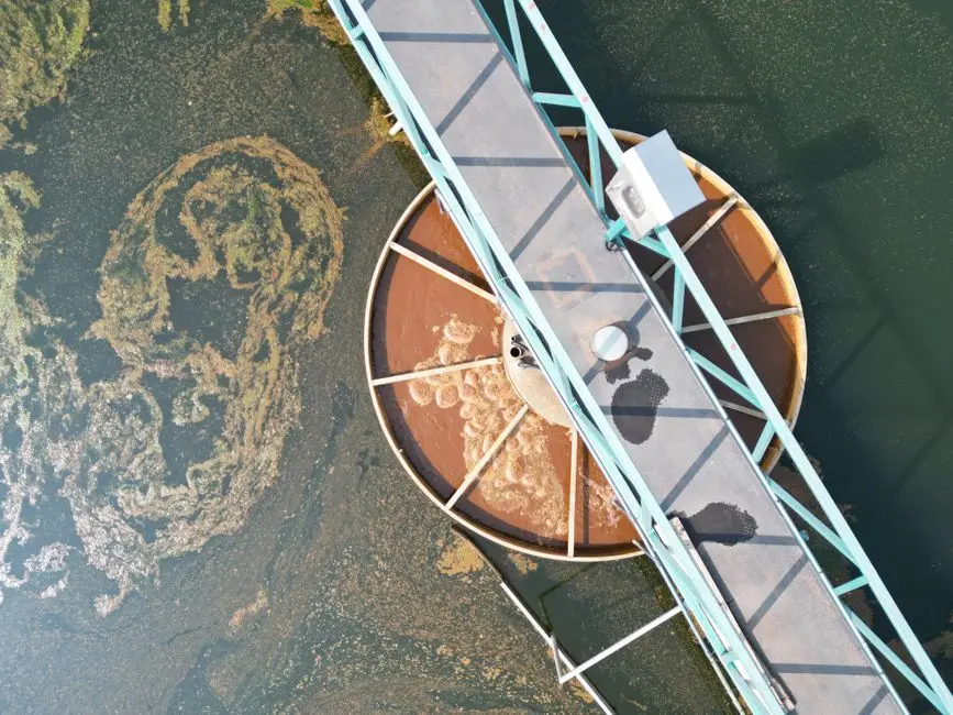
The job of the front end is straightforward: dampen the 3–5x diurnal COD swing from batch coating lines, knock down suspended solids, and strip emulsified resist before oxidation. Equalization tanks sized for 8–24 h HRT stabilize feed to the downstream train — anything shorter and the Fenton dose chases the peak rather than the average. pH adjustment to 7–8 with NaOH or H₂SO₄ precedes coagulation; PAC dosed at 200–500 mg/L paired with PAM at 2–5 mg/L removes 60–80% of SS and 20–35% of COD on optical film streams (per operator field data, 2026). A DAF flotation system then lifts the residual emulsified UV resist and oils at 4–25 m³/h per unit, with an air-to-solid ratio of 0.04–0.06 typical for this matrix. The DAF effluent should hit SS <80 mg/L and turbidity <30 NTU before it advances to oxidation. Chemical feed is handled by an automatic chemical dosing system tied to influent flow; a rotary mechanical bar screen ahead of equalization protects pumps from ragging and plastic film scraps that periodically shed from coating line cleanup. Sludge yield at this stage runs 0.4–0.8 kg DS per kg COD removed, which feeds forward into plate-and-frame filter press sizing — typically a 25–35% DS cake at 60–80% volume reduction with 3–6 kg polymer per tonne DS.
Advanced Oxidation: Fenton, Ozone and UV/H₂O₂
Advanced oxidation is the unit operation that lifts BOD/COD from 0.05–0.20 into the 0.25–0.40 range biology can actually metabolize, while degrading DMF, NMP, and acrylate monomers enough to cut toxicity. Fenton oxidation (H₂O₂/Fe²⁺ molar ratio 5–10, pH 3, HRT 1–2 h) delivers 40–70% COD removal on optical film streams at low CAPEX, but generates 3–5 kg Fe-sludge per kg COD removed — that sludge has to plate-and-frame pressed separately. Ozone (O₃ dose 1.0–2.5 g O₃/g COD, contact 30–60 min) hits 30–55% COD removal with no sludge carryover, but draws 8–12 kWh/kg O₃ and needs a destruct off-gas unit to keep worker exposure below 0.1 ppm. UV/H₂O₂ is reserved for trace solvents and color polish, typically paired with ozone on the polishing loop. Catalytic wet peroxide oxidation (CWPO) running at 60–80 °C removes 60–80% TOC and is the right pick for plants targeting zero-liquid-discharge where downstream RO brine would otherwise be unrecoverable. The decision rule is COD >8,000 mg/L → Fenton or CWPO; COD 3,000–8,000 mg/L with high color → ozone; polishing after bio → UV/H₂O₂.
| Technology | Best COD band | Removal | Sludge/energy | Fit |
|---|---|---|---|---|
| Fenton | 5,000–12,000 mg/L | 40–70% | 3–5 kg Fe-sludge/kg COD | High-COD solvent spikes |
| Ozone | 3,000–8,000 mg/L | 30–55% | 8–12 kWh/kg O₃ | Color & trace solvents |
| UV/H₂O₂ | <500 mg/L | 20–40% | Low sludge, moderate kWh | Polishing post-bio |
| CWPO | 5,000–10,000 mg/L | 60–80% TOC | 60–80 °C heat input | ZLD, brine prep |
Biological Stage: Hydrolytic Acidification + MBR
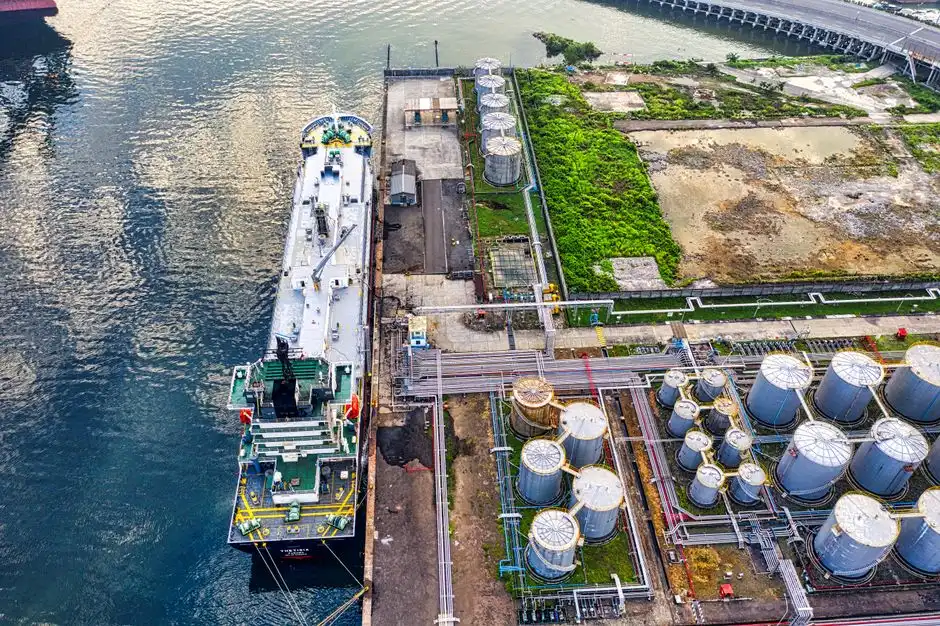
Post-oxidation, the residual COD is broken into short-chain organics in a hydrolytic acidification tank running at HRT 8–12 h and upflow velocity 0.5–1.0 m/h. This step reliably lifts BOD/COD by 0.05–0.15 on optical film matrices, transforming dimethylformamide degradation intermediates into volatile fatty acids the aeration stage can metabolize. The downstream MBR is sized with PVDF flat-sheet membranes at 0.1 µm pore, MLSS 8,000–12,000 mg/L, and HRT 18–30 h, with effluent SS <5 mg/L and turbidity <1 NTU. An A/O or A²/O configuration is required where TN <30 mg/L is the target; ammonium stripping is a useful adjunct for hydroxylamine-rich streams where free ammonia peaks. Reference operating envelope: HRT 24 h, COD loading 0.4–0.6 kg COD/m³·d, mixed liquor DO 2–4 mg/L, pH 7.0–7.5, temperature 25–35 °C. Long sludge age (SRT 30–60 d) holds excess sludge yield to 0.15–0.25 kg DS/kg COD removed — about a third of the yield from a conventional activated sludge plant. The integrated MBR wastewater treatment system and DF series PVDF flat sheet membrane modules are the workhorses for this step on lines of this size.
Reuse Stage: UF, RO and Zero Liquid Discharge Options
Membrane polishing turns the MBR permeate into a reuse-grade stream. UF at 0.01–0.05 µm protects the RO from residual colloids and biological carryover, running at flux 40–60 L/m²·h with transmembrane pressure 0.1–0.3 MPa. RO recovery sits at 65–75% with permeate conductivity under 50 µS/cm — well within the envelope for cleaning, HVAC humidification, and ultrapure makeup. Combined UF+RO gives system recovery of 80–90%, which is the design target for any optical film plant with a serious water budget. For sites pushing to zero liquid discharge, a brine concentrator plus MVR crystallizer running at 3–4 kWh/m³ produces a salt output reusable for road de-icing. Solvent recovery is the under-appreciated lever: DMF and NMP recoverable via distillation to 95–99% purity, with payback inside 12–24 months on lines above 1,500 m³/day. An industrial RO water treatment system sized for the MBR permeate flow is the standard skid for the reuse step.
| Reuse pathway | TDS target | Typical source | Pre-treatment |
|---|---|---|---|
| Cleaning / rinse makeup | <50 mg/L | RO permeate | UF + RO |
| Cooling tower makeup | <200 mg/L | RO blend with softened MBR | UF + RO (partial) |
| HVAC humidification | <50 mg/L | RO permeate | UF + RO |
| Toilet flushing | <500 mg/L | UF permeate | UF only |
2026 Compliance: Discharge Standards and Reuse Targets
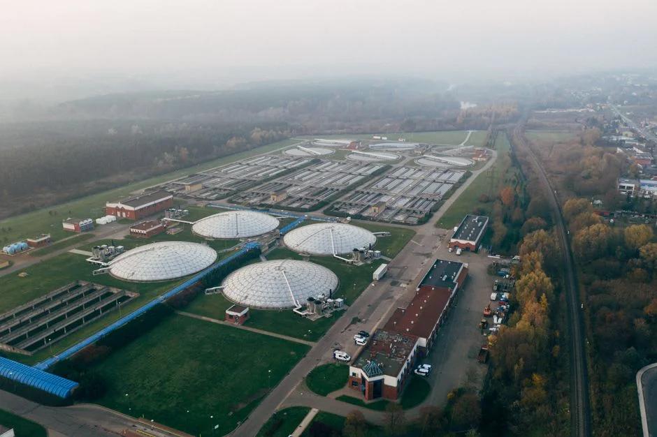
Compliance is no longer a single-number check. China GB 39731-2020 for electronic specialty materials sets COD ≤200 mg/L, NH₃-N ≤20 mg/L, TN ≤30 mg/L for surface water discharge — but local 2026 standards are tighter: Tianjin DB12/356 caps COD at 60 mg/L, Jiangsu DB32/939 at 80 mg/L, and Shanghai at 50 mg/L. Korea's KECO display-industry effluent ceiling is 120 mg/L COD; the Japanese equivalent sits at 160 mg/L. EU operators discharging similar streams fall under IED BAT-AEL of 30–60 mg/L COD, which effectively mandates the full MBR + RO train rather than MBR alone. The reuse pathway matters as much as the discharge number: cleaning and rinse makeup demand TDS <50 mg/L, cooling tower makeup <200 mg/L, toilet flushing tolerates <500 mg/L. A plant that hits 80–90% reuse can shrink its discharge consent volume proportionally and reduce permit risk on the residual stream.
| Region / standard | COD limit | NH₃-N | TN | Note |
|---|---|---|---|---|
| China GB 39731-2020 | 200 mg/L | 20 mg/L | 30 mg/L | Electronic specialty materials |
| Tianjin DB12/356 (2026) | 60 mg/L | 8 mg/L | 20 mg/L | Local override |
| Jiangsu DB32/939 (2026) | 80 mg/L | 10 mg/L | 25 mg/L | Local override |
| Shanghai (2026) | 50 mg/L | 5 mg/L | 15 mg/L | Strictest |
| Korea KECO | 120 mg/L | — | — | Display industry |
| EU IED BAT-AEL | 30–60 mg/L | — | — | Best available technique |
CAPEX, OPEX and ROI for a 2,000 m³/day Optical Film Plant
For a 2,000 m³/day optical film line, the full train (equalization + coagulation/DAF + Fenton or ozone + hydrolytic acidification/MBR + UF/RO) lands at USD 3.5–6.5 million CAPEX depending on whether the plant targets 60% or 90% reuse. OPEX sits at USD 0.6–1.1 per m³ treated, broken into power 40–50%, chemicals 25–30%, membranes 10–15%, labor 10–15%. Water reuse savings of 0.18–0.32 m³ reclaimed per m³ treated deliver payback on the membrane skid alone inside 18–30 months at industrial water rates above USD 0.5/m³. Sludge dewatering via a plate and frame filter press produces 25–35% DS cake at 60–80% volume reduction; the upstream high-efficiency sedimentation tank cuts sludge mass by another 20–30% before pressing. For cross-checking on display-panel economics, the TFT-LCD wastewater treatment cost guide provides a complementary CAPEX breakdown, and the acid-alkaline wastewater treatment system guide covers the etching-rinse pretreatment train that runs in parallel on most optical film sites.
| Cost band | Value | Notes |
|---|---|---|
| CAPEX (full train, 2,000 m³/d) | USD 3.5–6.5 M | EQ + DAF + Fenton/O₃ + MBR + UF/RO |
| OPEX | USD 0.6–1.1 /m³ | Power 40–50%, chemicals 25–30% |
| Membrane replacement share | 10–15% of OPEX | MBR + RO modules |
| Reuse savings | 0.18–0.32 m³/m³ | UF+RO recovery 80–90% |
| Payback (membrane skid) | 18–30 months | At water > USD 0.5/m³ |
| Sludge cake DS | 25–35% | 3–6 kg polymer/t DS |
Frequently Asked Questions
Q1 — What makes optical film wastewater different from generic chemical wastewater? It is solvent-heavy (DMF, NMP, DMSO, IPA), has a BOD/COD ratio below 0.2, and swings 3–5x across the day because coating and developing lines run in batches rather than continuously.
Q2 — Can I treat optical film wastewater with MBR alone? Not advisable. Without advanced oxidation upstream, residual COD stays above 800 mg/L post-MBR and the biology is unstable under solvent shock.
Q3 — How much water can a typical plant reuse? 80–90% with UF+RO polishing on a properly designed system, with permeate conductivity below 50 µS/cm suitable for cleaning and HVAC humidification.
Q4 — What is the most common failure mode on these lines? DMF/NMP solvent shock in the bio stage, where an under-equalized slug of developer rinse knocks out nitrification. Mitigated by 8–24 h equalization and Fenton or ozone pre-oxidation.
Q5 — Which standard applies to a polarizer plant in China in 2026? GB 39731-2020 plus the local standard — Tianjin 60 mg/L COD, Jiangsu 80 mg/L, Shanghai 50 mg/L. The local limit is the binding number for compliance design.
Related Equipment
- industrial RO water treatment system — specifications, capacity range, and technical data