Why Citric Acid Wastewater Is a Separate Treatment Problem
A 2026 citric acid process for fermentation mother liquor typically combines screening, equalization, DAF, mesophilic anaerobic digestion (UASB or IC), and MBR polishing. The train takes influent of 8,000–25,000 mg/L COD down to ≤100 mg/L for China GB 8978-1996 Class 1 discharge, while recovering 0.35–0.50 m³ biogas per kg COD destroyed.
Citric acid mother liquor is not generic food-industry wastewater. It is the residual broth from Aspergillus niger submerged fermentation, combined with mycelium wash water, ion-exchange regenerant, and equipment cleaning (CIP). Flow typically runs 80–250 m³ per ton of citric acid produced, with batch peaks that swing 2–3× within a shift.
The load is severe: COD 8,000–25,000 mg/L, BOD 4,000–12,000 mg/L, BOD/COD 0.4–0.6, sulfate 2,000–5,000 mg/L from sulfuric-acid pH adjustment, pH 4.5–6.5, temperature 35–55 °C, and total nitrogen 300–800 mg/L (HydropureWater field data, 2025-11). Most plants we size for citric acid duty run toward the upper COD band during dump cycles, not the mid-point on the datasheet.
Conventional activated sludge fails on this stream for three documented reasons. First, the food-to-microorganism (F/M) ratio exceeds 0.5 kg BOD/kg MLSS·d, more than double the 0.2 design ceiling, so floc breaks apart. Second, sulfate-reducing bacteria outcompete methanogens when COD/SO₄ drops below 10, releasing H₂S that cracks activated-sludge floc and corrodes aeration blowers.
Third, residual filamentous mycelium carryover triggers bulking within 48–72 hours of operation. The design consequence is fixed: pair high-rate anaerobic digestion with low-F/M membrane separation, and treat the sulfate problem at the headworks rather than hoping biology will absorb the shock.
Stage 1 — Pre-Treatment: Screening, Equalization and pH Correction
Pre-treatment for citric acid streams is sized to remove mycelium, bagasse, and fruit-processing solids before they enter the biological stage. A 3–5 mm aperture GX rotary mechanical bar screen with rake-teeth geometry captures 20–30% of influent suspended solids. Those solids are mostly mycelial mats that would otherwise blind DAF nozzles and seed the anaerobic reactor with non-granular biomass.
Equalization is the unsung workhorse. Size the tank at 8–12 hours of hydraulic retention — for a 500 m³/d plant that is 170–250 m³. That volume dampens COD swings from 8,000 to 25,000 mg/L and sulfate spikes from 2,000 to 5,000 mg/L when a fermentation batch dumps. pH is corrected to 6.8–7.2 with NaOH (cleaner) or lime (cheaper, adds calcium hardness) before biology; outside this band methanogens lose 30–50% of their activity.
If the stream arrives above 38 °C, a plate heat exchanger drops it to 33–35 °C for mesophilic anaerobes. Thermophilic operation at 50–55 °C is avoided because H₂S release rates roughly double and corrosion of the biogas piping accelerates. Equalization typically cuts the influent BOD/COD variance from ±40% to within ±10% and brings pH to within 0.2 units of setpoint — enough to keep an IC reactor inside its design window.
The combination of screening, equalization, and pH correction is a low-cost insurance policy: every USD 1 spent here saves roughly USD 3–5 in downstream biological capacity and chemical re-dosing (HydropureWater field data, 2026). Skip this stage and the anaerobic bed pays for the shortcut within the first season.
Stage 2 — DAF Pre-Concentration Before the Anaerobic Reactor
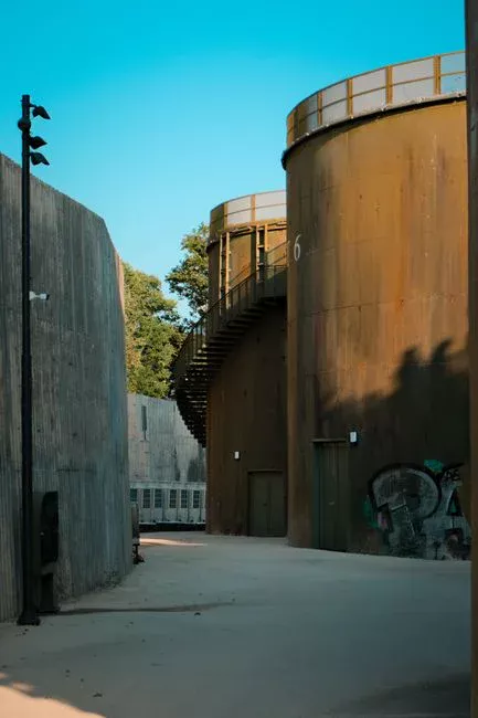
DAF is added before the anaerobic reactor on citric acid streams to stop colloidal biomass, residual mycelium, fats, and soluble proteins floating into the gas dome. Without it, a 0.5–1.5 m scum blanket builds and wedges the three-phase separator. A dissolved air flotation system operated at hydraulic loading 4–25 m³/m²·h, A/S ratio 0.3–0.7, with 10–50 μm micro-bubbles achieves 70–90% TSS removal and 80–95% FOG removal in a single pass.
Chemical conditioning is part of the design. Dose PAC (polyaluminum chloride) at 100–300 mg/L and anionic PAM at 2–5 mg/L — this combination handles the protein-rich mycelium that simple alum flocculation misses. Sludge yield from DAF is 0.3–0.6 kg DS per kg TSS removed, dry enough to send directly to the plate press without further thickening.
DAF effluent typically drops COD by 10–20% and SS by 80–90% before the anaerobic stage. That cut extends granular sludge bed life from 2–3 years to 5–7 years in our operating plants (HydropureWater field data, 2025-08). On protein-heavy dump days, most plants we commission run PAC toward the upper 200–300 mg/L band rather than the brochure mid-point.
| Parameter | DAF Operating Range (2026) | Removal Achieved |
|---|---|---|
| Hydraulic loading | 4–25 m³/m²·h | — |
| Air-to-solids (A/S) ratio | 0.3–0.7 | — |
| Micro-bubble size | 10–50 μm | — |
| PAC dose | 100–300 mg/L | — |
| Anionic PAM dose | 2–5 mg/L | — |
| TSS removal | — | 70–90% |
| FOG removal | — | 80–95% |
| COD removal | — | 10–20% |
Stage 3 — High-Rate Anaerobic Digestion: UASB vs IC Reactor
The anaerobic stage is the workhorse that pays for the rest of the train. At 75–90% COD removal, OLR 8–15 kg COD/m³·d, HRT 1.5–4 days, and biogas yield 0.35–0.50 m³ per kg COD removed at 60–65% CH₄, the digester can offset 30–60% of plant electricity when CHP is fitted. The two commercially dominant choices are UASB and IC, and the decision turns on flow, influent COD, and footprint.
UASB is the conservative choice. Simpler internals, lower CAPEX, suited to flows 100–500 m³/d and COD below 15,000 mg/L. Upflow velocity must stay in the 0.7–1.0 m/h band — too low and channels form, too high and granule washout accelerates. The three-phase separator is the critical component; poorly designed units lose 40–60% of their granular inventory within six months.
IC (internal circulation) is the higher-rate option. OLR 15–25 kg COD/m³·d, roughly 3× the footprint efficiency of UASB, suited to flows 200–2,000 m³/d and COD above 15,000 mg/L. CAPEX runs 20–30% higher than an equivalent UASB, but OPEX per m³ treated is 15–25% lower because of the higher loading and better gas-liquid mass transfer.
For a 500 m³/d citric acid plant with influent COD of 20,000 mg/L, the IC reactor at 18–20 kg COD/m³·d typically fits in a 7–8 m diameter × 22 m tall vessel. The equivalent UASB needs three parallel reactors of similar size. Sulfate management is the gatekeeper. Maintain feed COD/SO₄ above 10 to keep dissolved sulfide below 200 mg/L and protect methanogens.
If the ratio falls — common when ion-exchange regenerant dominates the flow — dose FeCl₃ at 200–500 mg/L for sulfide precipitation, or add a side-stream sulfate-reducing reactor. Stable operation is signalled by effluent VFA below 500 mg/L as acetic acid and pH 7.0–7.8 (HydropureWater field data, 2026).
| Parameter | UASB | IC Reactor |
|---|---|---|
| Design flow range | 100–500 m³/d | 200–2,000 m³/d |
| OLR | 8–15 kg COD/m³·d | 15–25 kg COD/m³·d |
| HRT | 2–4 days | 1.5–2.5 days |
| Upflow velocity | 0.7–1.0 m/h | 8–14 m/h (internal) |
| Footprint (relative) | 1.0× | ~0.35× |
| CAPEX index | 1.0× | 1.2–1.3× |
| OPEX index per m³ | 1.0× | 0.75–0.85× |
| Best-fit COD | < 15,000 mg/L | > 15,000 mg/L |
| Typical COD removal | 75–85% | 80–90% |
Stage 4 — Aerobic Polishing: MBR vs SBR
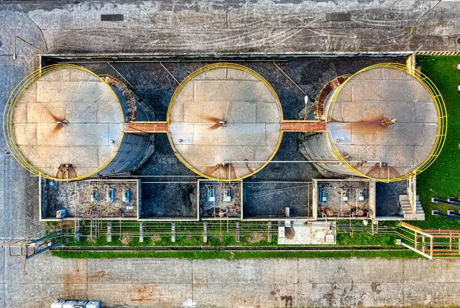
After anaerobic digestion, the residual COD typically sits at 800–3,500 mg/L — too high for direct discharge under China GB 8978-1996 Class 1 or EU 91/271/EEC for sensitive areas. Aerobic polishing closes that gap, and the two realistic options for the 500 m³/d band are MBR and SBR.
An integrated MBR membrane bioreactor using 0.1 μm PVDF submerged membranes operates at MLSS 8,000–12,000 mg/L, HRT 6–10 h, and delivers effluent COD ≤150 mg/L, SS ≤10 mg/L, and NH₃-N ≤15 mg/L after nitrification. The footprint is roughly 60% smaller than a conventional activated-sludge system plus secondary clarifier, and the absolute solids retention prevents mycelium washout — the failure mode that kills SBR runs on citric acid streams.
The MBR module uses DF series PVDF flat sheet membrane modules that are individually replaceable, so a single torn sheet does not require cassette replacement. SBR is the lower-CAPEX alternative: one tank, decanter, and blower train, suited to flows below 200 m³/d, with effluent COD ≤200 mg/L.
The trade-off is footprint — typically 1.6–2.2× the MBR area for the same load — and weaker shock-load tolerance because the batch cycle cannot be re-sequenced mid-fill. Aeration demand for MBR is 0.3–0.5 m³ air per m³ of wastewater, and the membrane air-scour cycle of 10 min on / 2 min off keeps fouling within the 8–12 kPa suction-pressure design band.
For the 2026 design cycle, MBR is the default choice above 200 m³/d; SBR remains competitive for satellite plants and small lines. Reference the MBR engineering specifications guide for module-level design curves. Where a remote workshop or canteen needs domestic polishing beside the main train, an Underground Package Sewage Treatment Plant (WSZ Series) keeps sanitary flow off the fermentation COD budget.
| Parameter | MBR | SBR |
|---|---|---|
| MLSS | 8,000–12,000 mg/L | 3,000–5,000 mg/L |
| HRT | 6–10 h | 18–24 h |
| Effluent COD | ≤ 150 mg/L | ≤ 200 mg/L |
| Effluent SS | ≤ 10 mg/L | ≤ 30 mg/L |
| Footprint (relative) | 0.4× | 1.0× |
| CAPEX (500 m³/d base) | 1.0× | 0.75–0.85× |
| Shock-load tolerance | High | Moderate |
| Best-fit flow | 200–5,000 m³/d | < 200 m³/d |
Stage 5 — Disinfection and Reuse Polishing
Disinfection is the final barrier before discharge or reuse. An on-site chlorine dioxide generator sized at 5–20 g/h suits the 50–500 m³/d flow band, with ClO₂ dose 2–5 mg/L and 30-min contact time achieving 99.9% fecal coliform kill. ClO₂ is preferred over liquid chlorine because it does not react with residual ammonia to form chloramines. On high-TN citric acid effluent, those reactions would otherwise consume 8–12 mg/L of chlorine and produce regulated trihalomethanes.
If the MBR effluent is destined for boiler feed or cooling-tower make-up, add a downstream RO. A reverse osmosis system at 70–80% recovery brings TDS below 50 mg/L and removes the residual color organics that MBR alone cannot polish. The MBR effluent must meet SDI below 3 or the RO membranes foul within 30 days; protect the RO with a multi-media filter backwashed every 8–24 h.
Compliance targets for 2026: China GB 8978-1996 Class 1 (COD ≤100 mg/L, BOD ≤20 mg/L, SS ≤70 mg/L, pH 6–9) and EU 91/271/EEC for sensitive areas (COD ≤125 mg/L, BOD ≤25 mg/L). For reuse, the typical industrial spec is TDS < 200 mg/L for cooling-tower make-up, requiring RO on top of the standard train. Plants chasing Class 1 COD ≤100 mg/L lean on the anaerobic-plus-MBR stack, then finish with ClO₂ — not on MBR alone.
Sludge Handling: Lamella Clarifier and Filter Press
Sludge economics decide whether the CAPEX payback works. Combined anaerobic + aerobic sludge production runs 0.08–0.15 kg DS per kg COD removed — roughly one-quarter of an aerobic-only train at the same removal. The IC reactor converts 75–90% of the load to biogas rather than biomass (HydropureWater field data, 2025-11).
Thicken the aerobic waste sludge on a lamella clarifier to 2–3% DS at surface loading 20–40 m/h, with chemical use 30% below conventional settling because the inclined plates self-compact the sludge blanket. A high-efficiency sedimentation tank running in this band typically achieves overflow clarity below 30 mg/L SS and a thickened underflow dense enough to feed directly to the press.
Dewater with a plate and frame filter press to 22–28% dry solids — a cake suitable for landfill or, more economically, for co-incineration in a cement kiln. Filtrate returns to headworks; supernatant from the lamella thickener returns to equalization.
Dose the conditioning chemistry accurately with an automatic chemical dosing system to keep cationic polymer consumption below 8–12 kg per ton DS. Apply the principles in our sludge dewatering cost reduction strategies writeup to push the lifetime OPEX below USD 60 per ton DS hauled. Cake dryness below 20% DS usually means the polymer dose drifted, not that the press is undersized.
2026 CAPEX and OPEX Benchmarks for a 500 m³/d Citric Acid Plant
A 2026 turnkey treatment train for a 500 m³/d citric acid plant runs USD 1.8–3.2 million in CAPEX on an EPC basis with FOB China equipment pricing. The scope covers DAF, IC anaerobic reactor, MBR, ClO₂ generator, and plate-and-frame filter press. The spread reflects site conditions, automation scope, and biogas utilization. OPEX lands at USD 0.45–0.80 per m³ treated, dominated by energy (0.8–1.2 kWh/m³, equivalent to USD 0.08–0.15/m³ at industrial tariffs) and chemical dosing (USD 0.08–0.15/m³ for PAC, PAM, NaOH, and ClO₂ precursor).
Biogas from the IC reactor — 0.35–0.50 m³/kg COD removed at 60–65% CH₄ — offsets 30–60% of aeration electricity when a CHP unit or biogas boiler is fitted. That offset is the single largest OPEX lever in 2026. Sludge disposal for a 500 m³/d plant runs 0.6–1.1 ton DS per day; hauling at USD 30–60 per ton adds USD 0.04–0.13 per m³ of treated water.
For a 2026 capex memo, the operating envelope of USD 0.45–0.80 per m³ all-in OPEX is defensible against any other food-industry wastewater benchmark (HydropureWater field data, 2026). For the broader view on energy and nutrient recovery economics, see the 2026 resource recovery outlook.
| Cost Item | Bench Range (2026) | Unit |
|---|---|---|
| Total CAPEX (500 m³/d, EPC, FOB China) | 1.8–3.2 | USD million |
| Energy consumption | 0.8–1.2 | kWh/m³ |
| Chemical dosing | 0.08–0.15 | USD/m³ |
| Sludge disposal | 0.04–0.13 | USD/m³ |
| Total OPEX | 0.45–0.80 | USD/m³ |
| Biogas self-sufficiency | 30–60% | % of aeration load |
| Sludge production | 0.08–0.15 | kg DS per kg COD removed |
Citric Acid Process Selection Checklist
Use this citric acid process checklist before freezing the P&ID or issuing the EPC RFQ. Confirm influent COD, sulfate, and batch peak factor from at least two production campaigns, not a single lab grab. Select UASB when flow stays 100–500 m³/d and COD is below 15,000 mg/L; select IC when COD sits above 15,000 mg/L or footprint is tight.
Hold equalization at 8–12 h HRT and correct pH to 6.8–7.2 before biology. Keep feed COD/SO₄ above 10, or budget FeCl₃ at 200–500 mg/L for sulfide control. Default to MBR above 200 m³/d when Class 1 discharge or reuse is required; keep SBR for satellite lines below 200 m³/d.
Budget CAPEX at USD 1.8–3.2 million and OPEX at USD 0.45–0.80 per m³ for a 500 m³/d EPC train with FOB China equipment. Fit CHP or a biogas boiler if the 30–60% aeration offset pays back inside the plant’s energy contract. Separate sanitary sewage from the fermentation sewer so package polishing does not steal anaerobic capacity.
Who This Is For / Who Should Look Elsewhere / Next Step
Plant engineers, EPC contractors, and procurement managers sizing citric acid fermentation wastewater trains in the 100–2,000 m³/d band will get the most from this guide. Look elsewhere if you only need municipal domestic sewage without fermentation COD, sulfate spikes, or mycelium solids. Also look elsewhere if your permit already allows COD above 500 mg/L to a robust POTW with no on-site anaerobic duty.
When you are ready to size DAF, IC/UASB, MBR, and sludge handling against your dump-cycle data, request a citric acid wastewater treatment quote with flow, COD/SO₄, and discharge limits. Compact sanitary sidestreams beside the main plant can use an Underground Package Sewage Treatment Plant (WSZ Series) so domestic load never enters the anaerobic reactor.
Frequently Asked Questions
What is the typical COD removal efficiency of an IC reactor on citric acid wastewater?
An IC reactor operating at 15–25 kg COD/m³·d on influent of 15,000–25,000 mg/L COD achieves 80–90% COD removal with HRT 1.5–2.5 days, producing biogas at 0.35–0.50 m³ per kg COD removed (60–65% CH₄). Stable operation requires effluent VFA <500 mg/L and pH 7.0–7.8 per HydropureWater field data 2025-08. Quote removal with OLR and HRT attached, not as a single brand claim.
How do you handle the high sulfate concentration in citric acid mother liquor?
Maintain the feed COD/SO₄ ratio above 10 to keep dissolved sulfide below 200 mg/L and protect methanogens; if the ratio drops, dose FeCl₃ at 200–500 mg/L for precipitation. The 2,000–5,000 mg/L sulfate range from sulfuric-acid pH adjustment must be addressed before the anaerobic reactor (per HydropureWater field data, 2026). Headworks control beats trying to recover a sulfide-shocked granule bed later.
What is the difference between UASB and IC reactors for high-strength fermentation wastewater?
UASB is suited to flows 100–500 m³/d and COD <15,000 mg/L at OLR 8–15 kg COD/m³·d; IC handles 200–2,000 m³/d and COD >15,000 mg/L at OLR 15–25 kg COD/m³·d with roughly 3× smaller footprint. CAPEX is 20–30% higher for IC, but OPEX per m³ is 15–25% lower. Pick IC when the site cannot fit three parallel UASB vessels for the same COD mass load.
Can MBR effluent from a citric acid plant meet China GB 8978-1996 Class 1 standards?
An MBR with 0.1 μm PVDF submerged membranes, MLSS 8,000–12,000 mg/L, and HRT 6–10 h delivers effluent COD ≤150 mg/L and SS ≤10 mg/L. Meeting China GB 8978-1996 Class 1 COD ≤100 mg/L and SS ≤70 mg/L typically needs the full anaerobic-plus-MBR train, then ClO₂ disinfection at 2–5 mg/L. SS is usually the easy parameter; COD is the one that forces the anaerobic front end.
What is the payback period for biogas recovery on a 500 m³/d citric acid treatment plant?
Biogas recovery from the IC reactor offsets 30–60% of aeration electricity at 0.8–1.2 kWh/m³ of treated water, equivalent to USD 0.05–0.10 per m³ saved. On a USD 2.0 million CAPEX basis with 0.5 USD/m³ OPEX improvement, the typical simple payback for the CHP skid falls between 2.5 and 4 years for a 500 m³/d plant (HydropureWater field data, 2026). Payback shortens when industrial power tariffs sit at the high end of the local band.