Define the Cho Lon wastewater design basis
A data center in Cho Lon needs two separately characterized waste streams: cooling tower blowdown and ancillary process wastewater. Blowdown carries concentrated dissolved solids, scaling species and cooling chemicals, so the treatment train should normally screen and filter the feed, control chemistry and pH, and then use the discharge route to determine whether softening, side-stream reverse osmosis, MBR polishing or direct sewer disposal is appropriate. The design basis is QCVN 40:2015/BTNMT, but the industrial-park WWTP inlet specification may be stricter and should become the binding basis. At 4 cycles of concentration, blowdown equals 25% of makeup water; sizing and equipment selection must therefore begin with a site-specific water balance.
Cooling tower blowdown and ancillary wastewater are not interchangeable. Cooling tower blowdown is the controlled purge from the evaporative cooling loop and contains concentrated dissolved solids, treatment chemicals and metals released by corrosion. Humidification, chiller bleed, once-through generator testing and other process drains must be sampled separately because their flow, chemistry, temperature and disposal route may differ. S3 requires both streams to be characterized before the treatment train is fixed.
QCVN 40:2015/BTNMT provides the national framework. S3 identifies Column A for discharges into water bodies used for domestic water supply and Column B for other receiving waters. A Cho Lon project should therefore establish the receiving route before applying limits: direct discharge, industrial-park WWTP, combined drainage or another authorized route. The park operator’s inlet specification may be tighter than national limits and therefore becomes the binding design basis for the equipment package.
S3 states outlet design points of pH 6–9 and temperature no higher than 40°C. TDS is permit-dependent and should not be treated as a universal national limit; the receiving operator may impose a lower value. During FEED, obtain written confirmation of the applicable permit column, industrial-park acceptance limits, sewer capacity, brine conditions and the authority responsible for approval.
| Design input | Evidence to document | Why it controls the decision |
|---|---|---|
| Waste streams | Separate flow and chemistry for CTBD, humidification, chiller bleed and other drains | Prevents a combined stream from masking incompatible contaminants or temperatures |
| Receiving route | WWTP inlet specification, direct-discharge route, sewer capacity and permit authority | Determines the binding outlet criteria and whether reuse is needed |
| Site conditions | Water source, salinity or groundwater-intrusion risk, cooling configuration, chemical program, IT load and expansion plan | Defines seasonal, phased and future treatment demand |
| Applicable limits | National framework, permit column and any stricter park limits | Prevents equipment selection against an incomplete discharge envelope |
Comparable route-selection questions are addressed in data-center blowdown treatment in a dry climate and data-center blowdown treatment in Europe, but the Cho Lon permit and water analysis must remain site-specific.
Calculate blowdown before selecting equipment
S3 states the governing identity exactly: blowdown fraction of makeup = 1/(CoC − 1). At 4 cycles of concentration, blowdown is 25% of makeup; at 6 cycles, it is 20%. Across S3’s stated Ho Chi Minh City working range of 3–5 cycles, the corresponding blowdown fraction is 20–33%. This calculation is the starting point for equipment sizing, not a substitute for the complete site water balance.
- Establish measured or forecast makeup flow for each cooling system and operating phase.
- Select the design cycles of concentration from cooling performance, source-water chemistry and the permitted discharge route.
- Apply 1/(CoC − 1) to calculate continuous blowdown.
- Add seasonal, startup, shutdown, sampling and other controlled purge flows.
- Cross-check the resulting water balance against evaporation and the project’s future IT-load cases.
S3 presents a 25–30 MW campus with approximately 1–2 ML/day of makeup at 4 CoC as producing approximately 250–500 kL/day of blowdown. This is a representative case for feasibility screening, not a Cho Lon design flow. A project should replace those assumptions with its own utility data, cooling configuration and planned expansion.
| Cycles of concentration | Blowdown fraction of makeup | Mass-balance calculation |
|---|---|---|
| 3 CoC | 33% | 1 ÷ (3 − 1) |
| 4 CoC | 25% | 1 ÷ (4 − 1) |
| 5 CoC | 20% | 1 ÷ (5 − 1) |
| 6 CoC | 20% | 1 ÷ (6 − 1) |
S4 cites U.S. Department of Energy guidance that increasing cycles of concentration from three to six can reduce makeup water by about 20% and blowdown by about 50%. That supports evaluation of operating changes and softening before a full recovery plant, but the site must still demonstrate the resulting concentration, scaling and discharge chemistry.
Do not size from one annual-average flow. Create seasonal and phased cases because source-water conductivity, cooling demand and future IT load can change both wastewater quantity and composition. An industrial cooling-water softener may increase permissible cycles, but its duty, resin demand and regeneration basis still depend on the site water balance and hardness analysis.
Map the contaminants that drive pretreatment
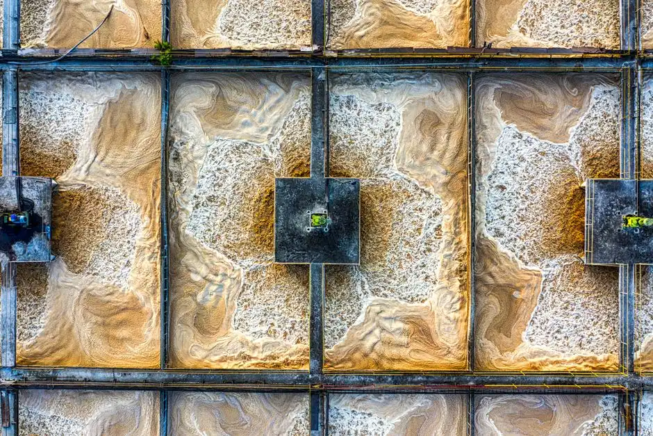
Cooling blowdown is a chemically altered stream rather than merely concentrated makeup water. S4 identifies elevated total dissolved solids, treatment chemicals and metals from corrosion. Those constituents determine the required screening, filtration, chemical control, membrane protection and residual-handling equipment.
S3 gives CTBD characterization ranges for design screening, not site acceptance values: TDS at 2–5 times the makeup concentration; silica at 20–80 mg/L after concentration, with a soft 150 mg/L ceiling at the RO inlet; copper and zinc at 0.1–1.0 mg/L; total phosphorus at 2–10 mg/L; residual oxidizing biocide at 0.1–0.5 mg/L; and pH at 8.0–9.0. Actual site analyses must replace these screening ranges before media, dosing or membrane selection.
| Characteristic | S3 screening range or design point | Engineering consequence |
|---|---|---|
| TDS | 2–5 times makeup | Drives salt concentration, conductivity and concentrate-management requirements |
| Silica | 20–80 mg/L after concentration; soft 150 mg/L RO-inlet ceiling | Controls antiscalant strategy and achievable recovery |
| Copper and zinc | 0.1–1.0 mg/L | Requires confirmation against receiving limits and suitable pretreatment |
| Total phosphorus | 2–10 mg/L | May affect discharge acceptance and chemical program |
| Residual oxidizing biocide | 0.1–0.5 mg/L | Influences biological treatment, membrane compatibility and discharge monitoring |
| pH | 8.0–9.0 | Supports scaling control but may require discharge-line pH trimming |
| Temperature | Cooling-loop blowdown at 30–35°C | May approach the stated 40°C outlet cap during hot periods |
Calcium carbonate, calcium sulfate and silica are the three scaling species cited by S3 that constrain recovery. Their saturation behavior must be checked in the RO concentrate, not only in the feed. Once scaling exceeds the membrane’s operating envelope, recovery and pretreatment requirements change; the design should use site-specific chemistry rather than transfer a recovery figure from another climate.
S3’s baseline pretreatment train uses a mechanical screen to remove basin debris, multimedia filtration, and PLC-controlled antiscalant and biocide dosing on a conductivity-triggered feed. The rotary mechanical bar screen provides intake protection, the multimedia filtration system removes suspended material before sensitive treatment stages, and the automatic chemical dosing system should implement the stated conductivity-triggered control logic.
Include pH and temperature management in the discharge train. S3 advises trimming pH on the discharge line rather than altering the cooling loop, because lowering loop pH can create a corrosive regime. Closed-loop glycol requires a separate containment and disposal plan: S4 notes that glycol normally remains contained, but accidental release or maintenance drainage can raise oxygen demand and toxicity.
Compare the four treatment pathways
S3 identifies four realistic pathways for Ho Chi Minh City data centers, but the choice should follow the permit, campus scale and operator capability rather than a preferred technology. Treat-and-discharge is the lower-complexity sewer option; softening reduces blowdown; side-stream RO recovers part of the water; full ZLD is reserved for sites where discharge constraints justify the additional energy and operator burden.
| Pathway | Process concept | Applicable site condition | Principal risk or trade-off |
|---|---|---|---|
| Treat and discharge | Screen, filtration and DAF or high-efficiency sedimentation, then sewer discharge | S3 assigns this route to sites below approximately 5 MW with strong sewer access | Lowest capital burden, but exposure to discharge cost and tighter WWTP acceptance limits |
| Softening and higher cycles | Sodium-cycle softening raises CoC from 4 to 6–7, reducing blowdown from 25% to 13–14% of makeup | S3 identifies approximately 5–30 MW colocation sites with lean staffing | Lower operational complexity than RO; requires hardness analysis, salt handling and residual management |
| Side-stream RO | 75–80% recovery; permeate returns to cooling makeup and concentrate follows an approved management route | S3 associates this pathway with approximately 20–100 MW hyperscale campuses where reuse and water capability justify it | Requires pretreatment, membrane maintenance, concentrate disposal and skilled operation |
| Full ZLD | RO, brine desalter and crystallizer | S3 generally places it above approximately 50 MW where a binding discharge-zero constraint exists | Highest capital and operating burden; crystallizer energy and residue disposal require explicit treatment |
Apply S5’s four-question screen before selecting equipment:
- Can the blowdown enter the receiving body?
- Can it enter the WWTP without additional treatment?
- Is on-site treatment required?
- Does the interceptor or WWTP have sufficient capacity?
This sequence prevents a technology-led design. A DAF system for oily and solids-bearing wastewater can support a treat-and-discharge train, while the high-efficiency sedimentation tank is the alternative clarification route identified by S3. For reuse, an industrial side-stream RO system must be evaluated with the concentrate route, not as a stand-alone skid. MBR polishing through the integrated MBR treatment system is justified where the required effluent or reuse quality demands it.
S3’s 15 MW benchmark reports 60% blowdown recovery, a 6.7-year base payback and a 3–5-year range after avoided costs, ESG value and permit-risk reduction are included. This is not a Cho Lon quotation or guarantee; it is a sensitivity case whose result depends on local tariffs, discharge conditions, recovery and capital scope.
Build the process train and residual-waste handling
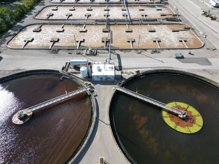
The side-stream RO process train should follow S3’s sequence: intake protection, multimedia filtration, conductivity-triggered antiscalant and biocide dosing, RO at 75–80% recovery, permeate return to cooling makeup and managed concentrate. Every stage should have a defined isolation, flush and bypass strategy so that one failure does not compromise the cooling loop.
Add DAF or lamella clarification where the analysis identifies suspended solids, colloidal material, oil and grease. DAF should be evaluated where floating contaminants must be removed, while lamella clarification can provide the settling function identified in S3’s baseline. The choice should follow the waste characterization rather than the preferred equipment name.
Use MBR polishing only where the effluent or on-site reuse specification justifies it. S3 describes MBR as bringing TSS below 1 mg/L and reducing bacterial load. This can support a reuse case, but it adds controls and maintenance that a sewer-discharge project may not need.
Manage warm discharge and pH on the final discharge line. S3’s guidance is to avoid changing the cooling-loop pH merely to satisfy an outlet limit. The chlorine dioxide generator may support microbial control where the selected process requires it, but biocide generation, residual monitoring and safety requirements must be matched to the chemical program and receiving limits.
Size residual handling around actual pretreatment and clarifier solids. S3’s baseline uses lamella clarification followed by a plate-and-frame filter press. Actual sludge volume must be calculated from site chemistry and chemical dosing because it is not established by blowdown flow alone. The design should define thickening, dewatering, storage, transport and the receiving waste stream.
Compare capital cost and payback
S3 gives indicative 2026 USD capital bands for the four pathways: treat-and-discharge in the low hundreds of thousands; softening in the mid six figures; side-stream RO from the mid six to low seven figures; and full ZLD from the high six to low seven figures. These are screening bands, not vendor quotations. Final pricing depends on flow, analysis, recovery, receiving-water route, civil scope and sludge handling.
| Pathway | S3 indicative 2026 capital band | Cost inputs to request from suppliers |
|---|---|---|
| Treat and discharge | Low hundreds of thousands of USD | Flow, pretreatment, DAF or sedimentation, pumping, controls, electrical and civil work |
| Softening and higher cycles | Mid six figures USD | Makeup and blowdown flow, hardness, resin, brine discharge, regeneration storage and controls |
| Side-stream RO | Mid six to low seven figures USD | Recovery, feed chemistry, pretreatment, membrane quantity, CIP, concentrate routing and building works |
| Full ZLD | High six to low seven figures USD | RO, desalter, crystallizer, energy, residue handling, redundancy and operator requirements |
The total-cost model must include electricity, antiscalant, CIP chemicals, membrane replacement, sludge hauling, brine or salt regeneration and crystallizer energy. These operating lines were identified by S3 as material to pathway comparison. Capital cost alone is not a valid comparison because the pathways produce different residual streams and different operator workloads.
S3’s 15 MW sensitivity case reports 60% blowdown recovery, a 6.7-year base payback and a 3–5-year range after avoided costs, ESG reporting value and permit-risk reduction are included. Because Cho Lon freshwater tariffs are lower than in arid operating environments, water-cost savings alone are a weaker economic case. Put avoided permit risk and ESG reporting value into the financial model as explicit value lines rather than treating them as unstated benefits.
The lamella clarifier cost and ROI buyer guide provides a related screening framework, but the data-center package should retain the site-specific water balance, permit conditions and recovery assumptions.
Complete permit and supplier due diligence

Permit acceptance and compatibility checks must precede final equipment selection. Obtain representative source-water and blowdown analyses covering TDS, conductivity, hardness, silica, chloride, phosphorus, copper, zinc, pH, temperature, residual oxidizing biocide and TSS. Use seasonal sampling where source-water quality varies, and obtain glycol drainage analyses separately.
| Due-diligence item | Written evidence required | Decision protected |
|---|---|---|
| Regulatory route | Applicable permit column, issuing authority and approved receiving route | Prevents reliance on an incorrect discharge basis |
| WWTP acceptance | Industrial-park inlet limits, sewer capacity and brine conditions | Confirms whether direct sewer disposal is viable |
| Water chemistry | Representative source and blowdown analyses, including seasonal variability | Sets media, membrane, dosing and recovery criteria |
| Supplier design | Design flow, variability, pretreatment criteria, membrane or media life and redundancy | Confirms that the package fits the actual water balance |
| Operations | Control philosophy, CIP requirements, power demand, spares and local service support | Tests maintainability and operator capability |
| Monitoring | PLC-controlled dosing, conductivity-triggered feed, flow measurement, pH adjustment and remote operation | Provides the controls identified in S3 |
| Residuals | Sludge, brine, salt and chemical-waste destinations | Prevents an untreated residual becoming a permit exception |
Request all of these in writing before the shortlist is finalized. A supplier should identify design assumptions, pretreatment criteria, membrane or media life, control philosophy, redundancy, CIP requirements, power demand and local service support. Unassigned limits should return to the permit owner or park operator rather than being transferred informally to the equipment vendor.
S1 provides a relevant precedent: the Palo Verde Nuclear Generating Station’s operating license required zero water discharge, and its evaporation ponds collected tower blowdown and other non-radioactive wastewater streams. It demonstrates that a future operating or permit restriction can change the technology choice. Design the preferred reuse strategy with a documented fallback route and reassessment trigger.
For maintenance spares and consumables, specify the required filter media, valves and treatment parts against the selected process rather than accepting a generic replacement list. The treatment-parts, valves and filter-media reference can support that comparison, but compatibility must be confirmed against the approved equipment design.
Frequently Asked Questions
How is cooling blowdown calculated for a Cho Lon data center?
S3 gives the formula: blowdown fraction of makeup = 1/(CoC − 1). That produces 25% at 4 CoC and 20% at 6 CoC. Apply the formula separately to each cooling configuration, then add evaporation, seasonal variation, sampling flows and other purge uses to complete the site water balance.
Which treatment pathway fits a small colocation site with lean operator staffing?
S3 identifies approximately 5–30 MW colocation sites as candidates for sodium-cycle softening and higher cycles of concentration. A buyer should request a site water balance, hardness analysis, regeneration and brine-disposal design, and operating staffing plan. Confirm that the resulting blowdown remains within the receiving route’s limits.
What capital budget should a buyer request for cooling blowdown treatment?
S3’s indicative 2026 capital bands range from the low hundreds of thousands of USD for treat-and-discharge to the high six to low seven figures for full ZLD; side-stream RO falls between the mid six and low seven figures. A binding quotation requires design flow, seasonal analysis, recovery, receiving route, civil scope and residual handling. Request both equipment and installed-cost pricing with exclusions identified.
Which discharge supplier should be selected for a Cho Lon data center?
QCVN 40:2015/BTNMT is the national framework, but S3 states that a tighter industrial-park WWTP inlet specification can become the binding design basis. Ask the receiving operator and permitting authority for the applicable column, inlet limits, sewer capacity and brine acceptance in writing. A supplier should then demonstrate that its proposed equipment meets that written acceptance envelope, not only the national framework.