Why Pimpri-Chinchwad Changes the Math for Data Center Water
Pimpri-Chinchwad sits inside a Pune district where PCMC municipal supply is rationed and Pawna reservoir allocation is contested politically; tanker dependence is already a documented cost line for large industrial builds, including hyperscale data centers. Indian data-centre policy in 2026 explicitly favours treated wastewater substitution for cooling-tower makeup where feasible, which makes reuse, not disposal, the regulatory default (S5). Closed-loop liquid cooling can recirculate more than 95% of its coolant, so the consumptive load is dominated by the cooling-tower outer loop — the same loop that produces CTBD (S5).
A 100 MW facility can use up to roughly 2 million litres of water per day, so even a single percentage point of freshwater offset translates into millions of litres per month at PCMC tariff and tanker rates (S2). For the engineer sizing the train, that means CTBD is the highest-leverage stream in the entire water balance, and the design target is to recover it for cooling-tower makeup rather than write it off as waste. CTBD, plainly, is the controlled purge from an evaporative cooling loop that prevents dissolved solids, scale, corrosion byproducts and biological growth from accumulating past safe limits (S1).
Cooling Tower Blowdown Chemistry: What the Plant Has to Handle
CTBD TDS typically runs 1,200–6,000 mg/L — about 4–8× the makeup water — and rises further when cycles of concentration are pushed higher (S1). At 4 cycles of concentration, roughly 25–30% of makeup water is lost to blowdown; a facility using 10 million gallons per month discharges 2.5–3 million gallons to blowdown (S1). Scaling minerals — calcium, magnesium, silica and alkalinity — concentrate in the loop and complicate downstream recovery, with silica and calcium sulfate the salts that cap conventional BWRO at 75–80% recovery (S1, S2). Treatment chemicals also accumulate: biocides, corrosion inhibitors, scale inhibitors and dispersants, with legacy chromate or high-phosphate programmes a particular reuse and discharge problem (S1). Suspended solids typically run 10–50 mg/L — corrosion products, biofilm fragments, airborne particulates — and the biological load (planktonic bacteria, algae, biofilm) must be addressed in any recovery train (S1). The implication for the engineer is straightforward: the feed envelope is brackish, scaling-prone and chemically active, and the RO/NF design has to be sized against that envelope, not against a generic municipal spec sheet. For a parallel Indian example, the companion India data-center blowdown guide for Vadodara works through the same chemistry in a different state context.
| Parameter | Typical CTBD Range | Design Implication |
|---|---|---|
| TDS | 1,200–6,000 mg/L (S1) | Drives osmotic pressure and RO operating pressure |
| Cycles of concentration | 4 typical; higher at leading sites (S1) | Sets blowdown as % of makeup |
| Blowdown as % of makeup | 25–30% at 4 cycles (S1) | 2.5–3 MGD from a 10 MGD/month facility |
| Silica, CaCO₃, CaSO₄ | Concentrate with cycles (S1, S2) | Caps conventional BWRO at 75–80% recovery |
| Suspended solids | 10–50 mg/L (S1) | Needs side-stream and UF pretreatment |
| Treatment chemicals | Biocides, inhibitors, dispersants (S1) | Reformulate to non-phosphate, membrane-compatible |
| Biological content | Planktonic bacteria, biofilm, algae (S1) | Biocide control + UF barrier |
Reuse, Discharge Compliance or ZLD: The 2026 Decision Framework
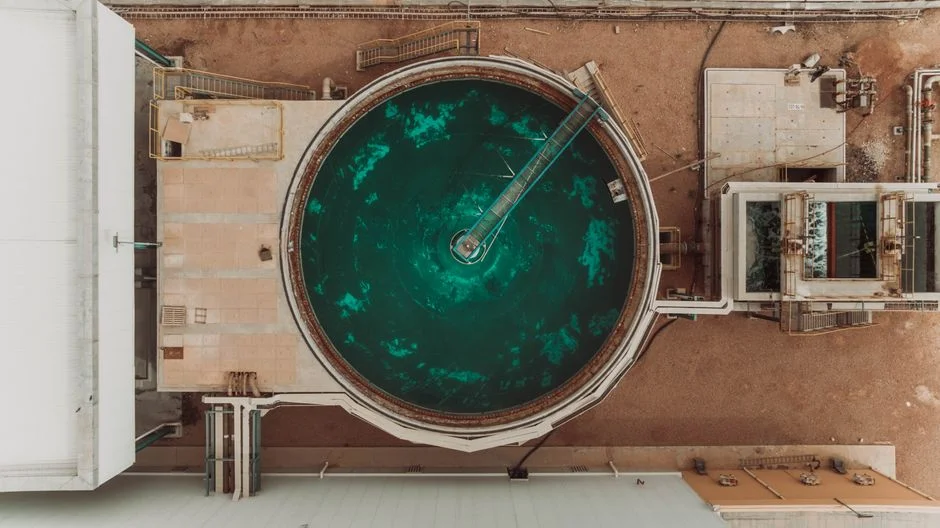
Three end-use strategies exist — reuse, discharge compliance, and zero liquid discharge — and each demands a different treatment train and economic logic (S1). Cooling-tower makeup reuse is the highest-value option, with 60–85% recovery, a direct freshwater offset and a cut in discharge volume (S1). Discharge compliance focuses on meeting MPCB consent limits for TDS, residual biocides, phosphorus and metals; the economic case is avoided discharge fees rather than water savings (S1). ZLD reaches 95–99% overall recovery and eliminates liquid waste entirely, but is justified only where discharge is truly impossible or freshwater alternatives are unavailable (S1). Most Indian hyperscale and colo sites in 2026 will land on reuse-first, with ZLD as a stretch case that the MPCB may effectively force when the regulator refuses any TDS-bearing discharge. The decision rule the engineer should carry into early design: pick the end-use objective first, then size the train — buying an RO before this choice is the most common scoping mistake on Indian data-center projects.
| End-Use Strategy | Recovery | Economic Lever | When It Fits 2026 PCMC |
|---|---|---|---|
| Cooling-tower makeup reuse | 60–85% (S1) | Freshwater + tanker offset, lower discharge | Default for hyperscale/colo in PCMC belt |
| Discharge compliance | Variable | Avoided discharge fees | When MPCB consent is the binding constraint |
| Zero liquid discharge | 95–99% (S1) | No liquid waste, freshwater independence | When regulator refuses any TDS-bearing discharge |
Building the Treatment Train: Pretreatment, Membrane Stage, Polishing
Step 1 is side-stream filtration sized at 1–5% of circulation flow, with a 10–25 micron rating and continuous self-cleaning spiral units in place of legacy sand or multimedia filters; CAPEX runs $50,000–200,000 for typical data-center installations (S1). Step 2 is ultrafiltration as RO/NF pretreatment, with 0.01–0.1 micron pore size, 10–30 psi operation, 90–95% recovery, permeate backwash, and chemical cleaning every 1–3 months (S1). Step 3 is reverse osmosis for dissolved solids, delivering 95–99% rejection, 10–50 mg/L TDS permeate, 150–400 psi operating pressure and 50–85% recovery in standard designs, with antiscalant injection mandatory (S1). Step 4 is high-recovery enhancement: controlled precipitation of silica, calcium carbonate and calcium sulfate as dense solids in a fluidized-bed reactor, paired with dynamic-mode RO operation, can lift overall recovery to roughly 95% with permeate silica around 1 mg/L (S2). Step 5, where the site is forced to it, is evaporative polishing — mechanical vapour compression at 95–98% recovery, distillate TDS below 10 mg/L, 15–25 kWh per 1,000 US gallons — used as the final stage in a multi-step train, not as a standalone (S1). Feed water to the membranes must be filtered below 10–15 microns, chemically conditioned against scaling and pH-adjusted; pretreatment is what determines whether the RO delivers its rated recovery (S1). For the unit operations themselves, see hollow-fiber ultrafiltration pretreatment for CTBD, the industrial RO train for cooling-tower blowdown recovery and multi-media filtration ahead of the RO membranes.
| Step | Unit Operation | Key Parameters | Notes |
|---|---|---|---|
| 1 | Side-stream filtration | 1–5% of circulation flow, 10–25 µm (S1) | $50,000–200,000 installed (S1) |
| 2 | Ultrafiltration (RO/NF pretreatment) | 0.01–0.1 µm, 10–30 psi, 90–95% recovery (S1) | Chemically cleaned every 1–3 months (S1) |
| 3 | Reverse osmosis | 95–99% rejection, 10–50 mg/L TDS permeate, 50–85% recovery (S1) | Antiscalant mandatory; 150–400 psi (S1) |
| 4 | High-recovery enhancement | Controlled precipitation + dynamic-mode RO, ~95% overall recovery, ~1 mg/L permeate silica (S2) | Pushes past the conventional BWRO ceiling |
| 5 | Evaporative polishing (MVC) | 95–98% recovery, distillate <10 mg/L TDS, 15–25 kWh/1,000 US gal (S1) | Final stage, not standalone (S1) |
Technology Selection: UF vs. NF vs. RO for CTBD Duty
UF (0.01–0.1 micron) removes suspended solids, bacteria, viruses and high-MW organics while passing dissolved salts; on CTBD it is pretreatment, not the dissolved-solids workhorse (S1). NF (75–150 psi) selectively removes hardness, sulfate and some dissolved solids while letting chlorides pass, with permeate TDS at roughly 30–50% of feed; it is the right pick when hardness is the limiting reuse or discharge parameter, not total TDS (S1). RO (150–400 psi) is the only membrane class that delivers the 10–50 mg/L TDS permeate that high-cycles cooling-tower makeup demands, with 50–85% recovery in standard designs (S1). The decision rule: a high-silica makeup stream pushes the engineer to RO for full silica removal; a calcium/magnesium-limited feed may be solved by NF at lower cost; a relatively clean blowdown with low biological load can be handled with UF alone, with RO or NF reserved for later expansion (S1). For a 50,000 GPD blowdown RO, CAPEX is $250,000–500,000 installed and OPEX is $1.50–3.00 per thousand gallons including energy, chemicals, membrane replacement and maintenance (S1). For ongoing maintenance, the engineer should plan for replacement RO and UF membrane elements for the CTBD train on a predictable replacement interval.
| Membrane | Pore / Pressure | Removes | Permeate / Recovery | CTBD Role |
|---|---|---|---|---|
| UF | 0.01–0.1 µm, 10–30 psi (S1) | SS, bacteria, viruses, high-MW organics (S1) | 90–95% recovery (S1) | Pretreatment to RO/NF |
| NF | 75–150 psi (S1) | Hardness, sulfate, partial TDS (S1) | Permeate 30–50% of feed TDS; 70–85% recovery (S1) | Softening-led reuse/discharge |
| RO | 150–400 psi (S1) | 95–99% of dissolved solids, silica, hardness (S1) | 10–50 mg/L TDS permeate; 50–85% recovery (S1) | High-cycles cooling-tower makeup |
Discharge, Reuse and Indirect Water: Closing the Indian Compliance Loop
Treated blowdown is reused as cooling-tower makeup, blended to keep cycles of concentration high and to cut both freshwater demand and discharge volume (S1). Where discharge is unavoidable, treated effluent must meet MPCB consent conditions under the Water Act 1974, and some jurisdictions enforce TDS below roughly 1,500 mg/L on the discharge stream, effectively forcing treatment of any concentrated blowdown (S1). National guidance and state policy in 2026 increasingly push operators towards treated wastewater substitution for cooling-tower makeup rather than continued freshwater draw (S5). Indirect water — the water embedded in the electricity that powers the IT load — is a substantial and often larger footprint than direct on-site use, so the Pune grid's coal share must be part of any honest water strategy (S3). Cooling-water chemistry has to be reformulated for compatibility with the recovery train, using non-phosphate, low-toxicity, membrane-compatible programmes, so the RO pretreatment is not poisoned by its own upstream chemicals (S1). The plant-side hardware that ties this together is the PLC-controlled antiscalant and pH dosing for the RO train and the on-site chlorine dioxide for cooling-tower biocide control.
Frequently Asked Questions
What CTBD flow and TDS should a Pimpri-Chinchwad hyperscale site design around in 2026?
For a CTBD stream the design envelope is 1,200–6,000 mg/L TDS, with 10–50 mg/L suspended solids and a silica and calcium-sulfate load that caps conventional BWRO at 75–80% recovery (S1, S2). A 100 MW facility can use up to roughly 2 million litres/day, with 25–30% of makeup water lost to blowdown at 4 cycles of concentration, so the engineer should ask the supplier for site-specific cycles-of-concentration data and the MPCB-side TDS ceiling that applies to any residual discharge (S1, S2). The MPCB discharge limit is not in the supplied research and must be requested from the site consent order before final sizing.
When does reuse-first stop being enough and ZLD actually pay back in Indian conditions?
ZLD reaches 95–99% overall recovery and is justified only when discharge is not permitted under any circumstances or freshwater alternatives are unavailable; CAPEX is in the $3–8 million band and OPEX is $5–15 per thousand gallons treated (S1). The Indian-specific check is whether the MPCB consent effectively prohibits any TDS-bearing discharge and whether the site's freshwater supply (PCMC plus tanker) is politically and economically constrained enough to justify that band. If neither condition holds, a partial ZLD that cuts discharge volume by 80–90% usually captures most of the water benefit at a fraction of the cost (S1).
What should a buyer ask a CTBD skid supplier before placing a PO?
Ask for UF and RO sizing matched to the site-specific CTBD envelope (1,200–6,000 mg/L TDS, 10–50 mg/L SS), an antiscalant programme matched to the silica and calcium-sulfate load, and Indian installation references on hyperscale or colo sites (S1, S2). Ask also for delivery and lead-time commitments with named dates, not ranges, and for evidence that the proposed RO can actually run at the recovery it has quoted once the Indian feed chemistry is layered in. A supplier who cannot answer those four points is not yet ready to be shortlisted.
What is the realistic CAPEX and OPEX band for a 50,000 GPD blowdown RO train in India?
A 50,000 GPD blowdown RO is $250,000–500,000 installed with OPEX of $1.50–3.00 per thousand gallons in the published US-context data, including energy, chemicals, membrane replacement and maintenance (S1). The Indian number will sit above that band once import duty, freight, INR–USD movement and civil works are layered in, and the engineer should request a landed-cost quote in INR with each line item broken out before comparing bids. The OPEX band should also be stress-tested against Pune grid power tariffs, since the RO's energy line is the largest swing factor.