Why Chennai Changes the Wastewater Math in 2026
Chennai's semiconductor fabs and data halls are clustered in the Sriperumbudur and Oragadam industrial belt, where municipal and industrial demand stresses the Adyar, Cooum, and Kosasthalaiyar catchments and where inter-basin Palar transfers are politically sensitive. Every additional cubic metre of withdrawal requires re-consenting, re-pumping, and additional costs. Globally, the semiconductor sector uses roughly 210 trillion litres of water per year, with about half consumed in water-scarce basins (TNFD, Feb 2026). A single fab can use around 14 billion litres of UPW per year, and a hyperscale data centre can exceed 2 billion litres of withdrawals per year (TNFD, 2026). 40% of existing fabs and over 40% of new fabs announced since 2021 are projected to be in basins with high or extremely high water-stress risk by 2030 (TNFD, citing Lepawsky 2024).
Tamil Nadu Pollution Control Board (TNPCB) consent orders for new and expanding industries in water-stressed blocks increasingly include reuse thresholds, zero-liquid-discharge (ZLD) expectations for high-COD streams, and third-party audit conditions. The design basis is therefore shaped by consent text long before unit operations are selected. The reuse logic discussed in industrial and municipal water reuse in 2026 applies, though the regulatory floor is set locally by TNPCB rather than by global best practice.
Process Wastewater Streams a Chennai Fab Must Segregate
Semiconductor wastewater consists of a stack of incompatible chemistries, including HF, HCl, H₂SO₄, and NH₃ residues; copper, nickel, and tungsten from deposition and chemical mechanical polishing (CMP); and solvents, photoresists, and PFAS (IDE Tech, 2026). Mixing these streams in a common drain converts a treatable problem into an irreversible one, because fluoride, low-biodegradable organics, and trace metals foul RO membranes and disrupt biological treatment. CMP alone typically represents 30–40% of a fab's total wastewater volume and requires slurry-resistant UF before it can rejoin any reuse loop (IDE Tech, 2026). PFAS compounds are chemically stable, resistant to conventional oxidation, and cannot be discharged untreated under emerging global rules (IDE Tech, 2026). Cooling-tower blowdown and hyperscale humidification bleed contain low organics but high TDS and silica, making them the most attractive streams for direct RO reuse or cooling-tower makeup. Each segregated stream acts as a separate consent line item, so upfront segregation reduces both compliance risk and the central plant footprint.
| Stream | Dominant Contaminants | Pre-RO Treatment Need | Reuse Potential |
|---|---|---|---|
| Acid/alkaline drains | HF, HCl, H₂SO₄, NH₃, variable pH | Stream-by-stream pH neutralisation | RO permeate after neutralisation |
| CMP wastewater | Silica/ceramic slurry, Cu | Slurry-resistant UF, metals precipitation | High — UPW or process rinse |
| Metals-bearing rinses | Cu, Ni, W, low pH | Precipitation or ion exchange | RO permeate after metals removal |
| Solvent / photoresist | Organics, surfactants, PFAS | AOPs (UV/H₂O₂, ozone) | RO permeate after AOP |
| Cooling-tower blowdown / data-hall bleed | TDS, silica, hardness | Softening, antiscalant | Highest — direct cooling-tower makeup |
Stream-by-stream segregation ensures the downstream treatment train is sized against accurate loads, which is necessary to make a BOD/COD balance defensible to a regulator. The parameter framing in BOD water treatment process limits and reduction methods applies to the organic-rich photoresist line, not to the fluoride or CMP streams.
Unit Operations: Building the 2026 Treatment Train
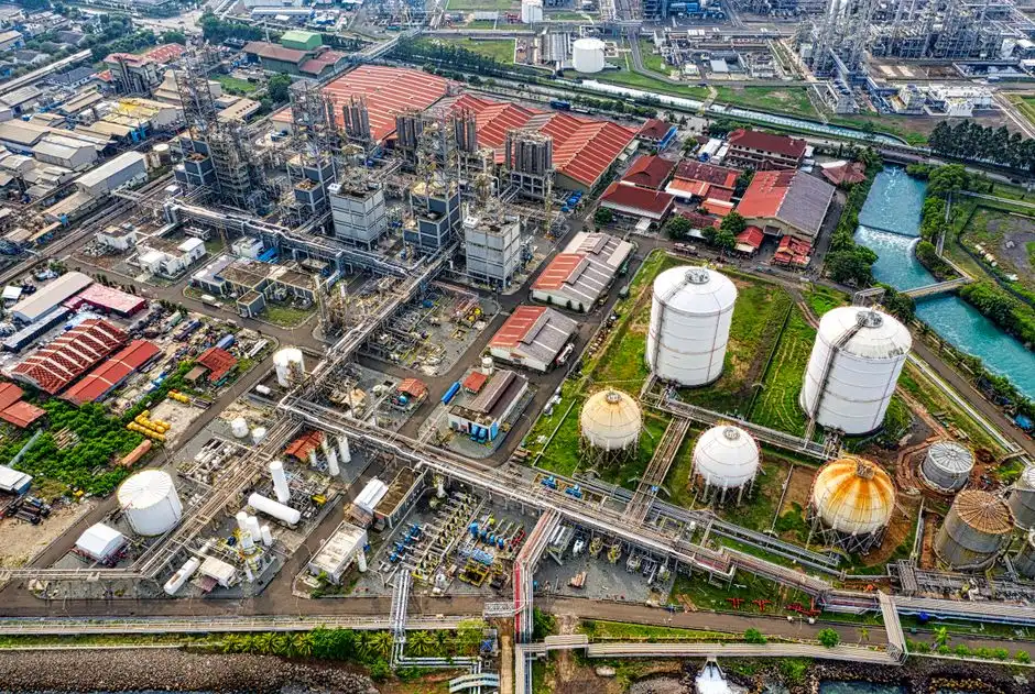
Equalisation and pH adjustment are required on every segregated line to keep downstream chemistry predictable and protect membranes (IDE Tech, 2026). Coagulation, flocculation, and lamella clarification strip suspended solids and precipitate metals before membrane duty, with a lamella clarifier for metals and TSS removal providing a smaller footprint than conventional clarifiers. A hollow-fibre UF system for CMP slurry polishing (~0.03 µm PVDF) handles turbidity swings that would otherwise blind a multimedia filter. An industrial RO system with up to 95% recovery performs bulk desalination, while advanced oxidation (UV/H₂O₂, ozone) is placed upstream of RO on solvent and PFAS lines to break down photoresists and improve performance (IDE Tech, 2026). A continuous electrodeionization polishing stack replaces mixed-bed ion exchange on the loop returning water to UPW, eliminating the regeneration wastewater stream. The brine reject (typically 10–15% of feed at 85–90% recovery) is sent to evaporation or crystallisation; ZLD is sized on the concentrate, not the total flow. The unit-operation stack is summarised below.
| Step | Unit Operation | Function | Notes for Chennai design |
|---|---|---|---|
| 1 | Equalisation + pH adjustment | Buffer hydraulic and chemistry shocks | One tank per segregated stream |
| 2 | Coagulation / flocculation / lamella | Suspended solids and metals precipitate | Sludge handled separately |
| 3 | UF (~0.03 µm PVDF) | CMP solids, turbidity reduction | Automatic backwash + air scour |
| 4 | AOP (UV/H₂O₂, ozone) | Photoresists, solvents, PFAS partial | Required before RO on organic lines |
| 5 | High-recovery RO | Bulk desalination, 85–90% reuse | Antiscalant tuned to fab chemistry |
| 6 | EDI / polishing loop | Final ion and silica trim for UPW reuse | No regeneration wastewater |
| 7 | Evaporation / crystallisation | Brine concentrate handling | Sized on 10–15% reject only |
State-of-the-art fabs recover 85–90% of their wastewater using high-recovery RO, advanced filtration, and thermal polishing, with hybrid high-shear RO targeting 90%+ (IDE Tech, 2026). For organic-rich streams that resist RO, a parallel MBR system for organic-rich fab streams can be inserted ahead of RO to reduce BOD/COD and protect the membrane from biofouling.
High-Recovery RO vs Hybrid MLD vs Full ZLD: Chennai Trade-offs
Three credible 2026 recovery architectures are available to engineers: high-recovery RO with polishing loops, hybrid MLD/ZLD, and full ZLD. High-recovery RO is the default for new fabs targeting 85–90% reuse because it minimises energy use per cubic metre and avoids thermal evaporation costs for most of the flow (IDE Tech, 2026). Hybrid MLD/ZLD applies high-recovery RO first, then routes only the concentrate to evaporation or crystallisation, which is the most common 2026 path when TNPCB consent or on-site water scarcity pushes the plant above 90% reuse. Full ZLD from day one is rare outside India due to high energy costs; in Tamil Nadu, full ZLD is typically reserved for high-COD specialty streams where the regulatory alternative is a discharge ban. The CMP wastewater CAPEX comparison for 2026 and the hybrid ZLD system design case provide equipment-level analysis, though the consent drivers remain Chennai-specific. The decision drivers and a head-to-head comparison are summarised below.
| Architecture | Typical Recovery | Energy Posture | Best Fit in Chennai |
|---|---|---|---|
| High-recovery RO + polishing | 85–90% | Lowest kWh per m³ reused | New fabs in blocks without ZLD mandate |
| Hybrid MLD/ZLD (RO + evap/crystalliser on concentrate) | ~95–99% | Concentrate-only thermal load | Water-stressed blocks, high reuse consent |
| Full ZLD | ~99.8%+ | High thermal and CAPEX | Photoresist and high-COD specialty streams |
Chennai-specific decision drivers include consent conditions, raw-water and energy tariffs, available land for evaporation ponds, and whether a co-located data hall can absorb cooling-tower blowdown. Hybrid MLD/ZLD is the architecture most likely to satisfy both TNPCB reuse thresholds and procurement's CAPEX envelope on a Sriperumbudur site in 2026.
Data-Halls and Fabs: Sharing the Drain
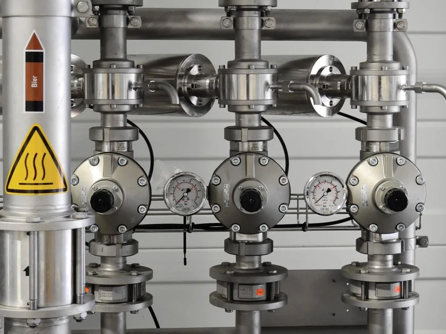
A typical data centre uses 25 million to 770 million litres of water per year, and hyperscale facilities can exceed 2 billion litres annually (TNFD, 2026). Roughly 45% of data centres globally sit in river basins at high risk of water-availability disruption, making reuse a permit condition rather than a sustainability goal (TNFD, citing NatureAlpha/NatureFinance 2025). In the Sriperumbudur / Oragadam belt, fab and data-hall operators are increasingly co-located because they share identical constraints regarding power, land, fibre, and water. The shared-infrastructure opportunity allows RO reject from the fab polishing loop to be blended into the data-hall cooling-tower makeup after hardness and silica checks; similarly, data-hall humidification bleed can be recovered through the same CIP/RO train as low-strength fab rinses. Success depends on front-end engineering design, as HVAC, drainage, and consent lines must be planned together to avoid uneconomic retrofits. The data-hall cooling blowdown design reference and the parallel fab-and-data-hall engineering guide for Europe cover the co-location logic under various regulatory regimes.
Frequently Asked Questions
What is the realistic reuse target a Chennai fab should design for in 2026?
State-of-the-art fabs recover 85–90% of wastewater using high-recovery RO plus polishing, with hybrid configurations pushing toward 90%+ (IDE Tech, 2026). A Chennai plant should size its consent and pipework for at least 90% reuse, with concentrate routed to evaporation to ensure the regulatory case remains defensible if TNPCB conditions tighten.
Which streams should be segregated versus blended at the head of the plant?
Acid/alkaline, CMP, metals-bearing, solvent/photoresist, and cooling-tower blowdown must be on segregated lines because fluoride, abrasive silica, dissolved Cu/Ni/W, photoresists, and PFAS cannot be mixed without destroying downstream RO and biological steps (IDE Tech, 2026). Cooling-tower blowdown and data-hall humidification bleed are the only streams clean enough to blend or feed RO directly.
What should a buyer request from a supplier to compare CAPEX and OPEX on a Chennai hybrid MLD/ZLD plant?
Request a sized quotation broken down by unit operation (equalisation, lamella clarifier, UF, AOP, high-recovery RO, EDI, evaporator/crystalliser), a guaranteed recovery percentage at design feedwater quality, specific energy in kWh per m³ of permeate, and a separately priced annual antiscalant and membrane-replacement schedule. These line items are required to compare bids for the same headline recovery on a like-for-like basis.