Why Seafood Wastewater Demands a Purpose-Built DAF
A seafood processing plant generates three distinct wastewater streams, and a single set of municipal DAF numbers will not handle any of them correctly. Blood water from killing and bleeding carries several thousand mg/L of COD with elevated ammonia; process wash water dominates the suspended solids and FOG load; cook and cooling water arrives hot (often 45–70 °C) and carries emulsified fish oils that defeat coarse-bubble flotation. Each stream needs its own screening, equalization, and DAF set-point, and most operating problems in the field trace back to treating them as a single combined flow (S5).
The compliance picture is unforgiving. Seafood effluents routinely exceed discharge limits for TSS, FOG, COD, and total nitrogen/phosphorus, and the variability between shifts is wider than in any other food sector because raw-material throughput drives both flow and load (S5). Generic municipal DAF specifications — hydraulic loadings tuned for low-FOG influent, alum-only chemistry, modest recycle — translate into undersized units, unstable floats, and chronic FOG breakthrough.
There is a microbial risk that physical flotation does not solve. A 2026 study of two Tema, Ghana seafood processing facilities documented median coliform counts of 920 and 280 MPN/100 mL before treatment upgrades; after upgrades, those counts fell to 35 and 9.5 MPN/100 mL — a 96% reduction — but multidrug-resistant E. coli and Pseudomonas aeruginosa persisted, and resistance to third-generation cephalosporins remained detectable in effluent leaving the plant (Wallace-Dickson et al., Life, 12 Jan 2026, doi:10.3390/life16010107). DAF removes solids; it does not disinfect. Disinfection has to be specified separately.
Pilot data on fish-processing wastewater confirm that DAF, correctly configured, removes nearly all oil and grease and produces measurable drops in COD, turbidity, and phosphorus, while generating a float that can be valorised for proteins, oils, and nutrients (S2; S5). The design work is what separates a working seafood DAF from a chronic underperformer.
Influent Characterization: Building the DAF Design Basis
Design begins with a stream-by-stream matrix, not a single composite number. The table below summarises the typical ranges documented for fish and shellfish processing effluent, the three internal streams an engineer must segregate, and the DAF design implication of each (S5; cross-checked against S2 pilot data).
| Parameter | Blood water | Process wash water | Cook / cooling water | Typical composite range (S5) | Design implication for DAF |
|---|---|---|---|---|---|
| COD (mg/L) | 2,000–10,000+ | 800–4,000 | 1,500–6,000 | 1,000–8,000 | Drives equalization and biological load; pre-DAF screening mandatory |
| TSS (mg/L) | 500–2,000 | 800–5,000 | 200–1,500 | 500–3,000 | Sets air-to-solids ratio and float sludge yield |
| FOG (mg/L) | 200–1,000 | 500–3,000 | 1,000–5,000+ | 200–2,000 | Sets hydraulic loading toward the low end of 5–15 m/h and demands tighter microbubble distribution |
| Total nitrogen (mg/L) | 100–400 | 30–120 | 20–80 | 50–250 | Biological polishing required after DAF; consider anoxic zone |
| Total phosphorus (mg/L) | 10–40 | 10–60 | 5–30 | 10–50 | Coagulant (FeCl₃ or PAC) dose must be sized for P, not just TSS |
| Temperature (°C) | 10–25 | 10–30 | 40–70 | 15–45 (composite) | Hot cook water must be pre-cooled to ≤35 °C to protect biology and DAF microbubble stability |
| Salinity / TDS (mg/L) | Low–moderate | Variable (brining) | Low–moderate | 500–15,000+ (marine species, brining) | Conventional alum loses effectiveness; cationic polymers or PAC preferred |
Three numbers anchor the design. First, blood water can dominate the COD load even though it is a small fraction of the flow — segregating it into a dedicated equalization tank prevents shock loading. Second, cook-water temperature swings depress micro-bubble efficiency by lowering gas solubility and increasing float turbulence; pre-cooling or a dedicated equalization cell is required. Third, marine and brining effluents shift coagulant chemistry because chloride competes with hydrolysing metal coagulants; jar-testing with the actual TDS matrix is the only way to set a defensible polymer dose. The 96% coliform reduction reported at the Tema plants (Wallace-Dickson et al., 2026) is the upper bound of what physical-chemical treatment alone can deliver — disinfection downstream is non-negotiable.
Core DAF Design Parameters for Seafood Effluent
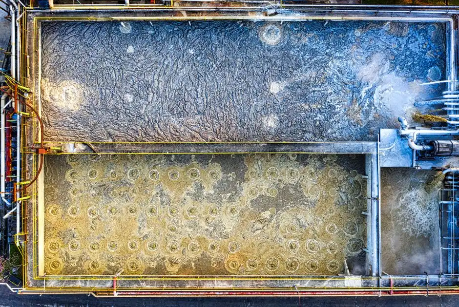
The numbers below are the working envelope a process engineer should put on a seafood DAF datasheet, and they are tighter than the generic industrial ranges because FOG, protein, and salinity stress the flotation step (S5; pilot data from S2).
| Parameter | Seafood DAF design range | Why it matters for fish/shellfish effluent |
|---|---|---|
| Hydraulic loading rate | 5–15 m/h; sit at 5–8 m/h for high-FOG cook-water streams | Higher FOG/TSS pushes the design toward the lower end to keep bubble contact time and float stability adequate (S5) |
| Recycle rate | 20–50% of throughput, often 30–40% for seafood | Higher recycle raises air-to-solids ratio without raising main-flow turbulence; needed for emulsified fish oils |
| Air-to-solids (A/S) ratio | 0.02–0.05 kg air / kg TSS | Below 0.02 floats are thin and unstable; above 0.05 wastes compressor energy and can break the float layer |
| Saturation pressure | 4–6 bar, typically 5–6 bar for seafood | Higher pressure dissolves more air and produces the 20–40 µm bubbles needed to lift emulsified fats (S5) |
| Microbubble size | 20–80 µm; target 20–40 µm for FOG capture | Tight microbubble distribution outperforms coarse bubbles on emulsified fish oils (S5; pilot confirmation S2) |
| Flocculant / coagulant dose | Cationic polymer 1–10 mg/L; PAC or FeCl₃ 50–200 mg/L where P removal is targeted | Jar-test against actual effluent; conventional alum underperforms at high TDS (S5) |
| Contact-zone retention | 1–5 minutes; 2–3 min typical | Short retention protects against septic odor in warm fish effluent and limits gas breakout |
| Float removal | Automatic hydraulic or paddle skimmer; manual only on small packaged units | Seafood float reaches 3–6% TS; auto-skimming keeps up with shift-to-shift load swings |
| Pre-treatment | Rotary bar screen 1–3 mm aperture upstream of DAF | Protects nozzles, reduces DAF TSS loading, and avoids ragging the saturator |
Three rules of thumb follow from the table. First, when in doubt, slow the hydraulic loading and increase the recycle before adding chemistry — the bubble contact time is the cheapest FOG removal you can buy. Second, jar-test every polymer against the actual TDS and temperature, because marine and brining matrices shift the optimum dose by a factor of two or more. Third, design the float handling for at least 3% dry solids; seafood floats are wetter than the textbook 5–8% because of the high protein and oil content. A deeper treatment of saturator design and microbubble generation is available in the 2026 DAF engineering specifications guide.
Worked Sizing Example for a 500 m³/day Fish-Processing Plant
The sequence below turns the parameter table into a defensible design memo. Assume a small-to-mid-scale whitefish and surimi plant with a 16-hour production shift, two daily clean-in-place (CIP) cycles, and a thawing room discharge.
- Derive design flow from peak production. Average day flow is 500 m³/day over 24 hours, but a 16-hour production shift means 31.3 m³/h average. Add a 1.5× peaking factor for CIP, thawing water, and shift-end dumps: design flow Q = 47 m³/h. Do not size DAF on the 24-hour average.
- Assign loadings from the stream matrix. Use the composite ranges (S5) and S2 fish-processing pilot data: TSS ≈ 2,000 mg/L, FOG ≈ 1,500 mg/L, COD ≈ 4,000 mg/L, total nitrogen ≈ 120 mg/L, total phosphorus ≈ 30 mg/L. At Q = 47 m³/h, that is 94 kg TSS/h and 70 kg FOG/h — both well above what a generic municipal DAF sees.
- Size equalization. Buffer ≥8 hours of design flow to absorb CIP peaks: 47 × 8 = 376 m³ working volume. Add 20% freeboard. Hot cook-water streams need a dedicated cooled cell sized for ≥2 hours of cook-water flow.
- Calculate DAF surface area. At a hydraulic loading of 6 m/h (chosen low because of FOG > 1,000 mg/L): A = Q / loading = 47 / 6 = 7.8 m². Round up to the next standard unit — typically 8–9 m². Confirm width-to-length ratio ≥ 4:1 to keep flow distribution stable.
- Calculate air demand and recycle. Target A/S = 0.04 kg/kg. At 94 kg TSS/h, air required = 3.8 kg/h. At 35% recycle, 16.5 m³/h of saturated recycle is needed. Saturator pressure 5.5 bar gives ~70 g air/L of recycle, so a 100-L saturator with a dedicated 5–7 kW compressor and a 20 m³/h recycle pump covers the load.
- Size the chemical dosing skid. Specify a HydropureWater automatic chemical dosing skid sized for PAC 50–200 mg/L (2.4–9.4 L/h at 10% solution) and cationic polymer 1–10 mg/L (47–470 mL/h at 0.5% solution). Use variable-speed drives and online streaming-current control for load following.
- Verify float handling. At 94 kg TSS/h and 3–6% TS in the float, the float pump handles 1.6–3.1 m³/h of sludge. Confirm downstream dewatering capacity on a HydropureWater plate and frame filter press sized for ≥50 kg dry solids per cycle.
- Specify inlet screening. Install a HydropureWater GX rotary bar screen with 2 mm aperture ahead of the DAF to remove scales, fins, and packaging debris that would otherwise foul nozzles and the saturator.
The result is a 7.8–9 m² DAF unit operating at 35% recycle and 0.04 A/S — defensible, reproducible, and tied to documented seafood effluent ranges (S5; S2).
Downstream Architecture: DAF → MBR → UF for Reuse
DAF is the front end, not the answer. It removes FOG and most TSS but leaves the soluble BOD/COD that defines the effluent (S5). What comes after depends on whether the plant is discharging to a municipal sewer or reusing water in-process.
For a sewer discharge, a conventional activated-sludge stage after DAF achieves roughly 90% BOD reduction on biodegradable fish effluent (S5). For shock-prone operations, an MBR is the better fit: biomass is fully retained by the UF membranes, so mixed liquor suspended solids run 5× higher than in a conventional aeration tank, and the system can buffer inlet BOD spikes up to 10 g/L without losing permeate quality (S5). MBR also produces 0.05–0.1 kg of excess sludge per kg BOD removed, compared with 1–3 kg/kg for a conventional plant — a material reduction in sludge handling and dewatering cost (S5). DAF supports this by thickening float sludge 4–5× more than a secondary clarifier, shrinking the volume that has to be dewatered (S5).
For water reuse, follow MBR with a dedicated UF polish (0.03–0.1 µm). The combined train produces a permeate suitable for non-contact reuse — wash-down, boiler feed pre-treatment, or cooling-tower make-up after further polishing (S5; S2). Pilot work on fish-processing wastewater has also demonstrated biochar column filtration after DAF for residual nutrient adsorption, with hemp biochar removing N and COD while spruce biochar captures P; the loaded biochar recovers 9.1–10.5 mg/g N and 0.32–1.38 mg/g P and is suitable as a soil conditioner (S2).
Disinfection closes the train. The Tema study found that even after upgrades that cut median coliform counts by 96%, multidrug-resistant gram-negative bacteria and third-generation cephalosporin resistance persisted in the final effluent (Wallace-Dickson et al., 2026). For any plant discharging to a sensitive receiving water or reusing water on-site, specify UV or chlorine dioxide after MBR/UF. A HydropureWater MBR system followed by a HydropureWater UF system and a HydropureWater chlorine dioxide generator addresses the AMR persistence risk that physical-chemical DAF cannot.
2026 Selection Framework: Matching DAF Config to Plant Reality
Translate the engineering into a purchase by matching DAF model size to peak hourly flow, not daily average — undersizing for the shift-end CIP dump is the single most common field failure. HydropureWater's DAF product line covers 4–300 m³/h across 13 standard models, so a 500 m³/day plant with a 47 m³/h peak flow sits in the lower-mid range, and a 5,000 m³/day surimi plant with 300+ m³/h peaks still fits the catalogue without field-assembled skids (HydropureWater verified product catalog, 2026).
For high-FOG cookers, surimi lines, and tallow-recovery operations, specify the unit in heavy-oil mode: higher recycle (35–50%), saturation pressure at 5.5–6 bar, and tighter microbubble distribution in the 20–40 µm band. For plants targeting reuse, budget the full train — DAF plus MBR plus UF plus disinfection — not DAF alone, and size the equalization tank to absorb at least 8 hours of peak flow. For plants discharging to a municipal sewer, the priority is meeting local FOG limits (typically 50–100 mg/L) at the DAF outlet so the downstream municipal plant can stay in compliance, with biological polishing only as needed. For plants with limited footprint, packaged DAF units with integrated saturation, skimming, and control panel reduce field assembly time and the risk of control mismatches between separately sourced skids.
The right starting point is a HydropureWater DAF system sized to the peak hourly flow with the heavy-oil option enabled; the rest of the train — MBR, UF, disinfection, dewatering — is specified against the discharge or reuse target, not the DAF datasheet. A more detailed DAF selection decision matrix is in the best DAF unit selection framework, and a head-to-head with CPI and API separators is in the oil and grease removal technology comparison. For an analogous food-industry reuse train with UF as the polish step, see the UF system engineering guide for food processing wastewater.
Frequently Asked Questions
How much FOG can a DAF actually remove from seafood effluent?
Properly sized DAF with cationic polymer dosing at 1–10 mg/L, A/S ratio 0.02–0.05, and microbubbles in the 20–40 µm range routinely removes more than 90% of FOG and TSS from fish-processing wastewater, with measured removals in pilot work described as "nearly all" oil and grease (S2; S5). Composite seafood effluent can carry 200–2,000 mg/L FOG, so even 90% removal leaves an outlet that needs biological polishing to meet a 50–100 mg/L sewer discharge limit.
Is DAF enough on its own for fish processing wastewater?
No. DAF removes FOG, TSS, and a portion of COD, but the soluble BOD/COD load — typically 1,000–8,000 mg/L in the composite stream (S5) — still requires biological treatment. Aerobic activated sludge after DAF delivers ~90% BOD reduction; an MBR delivers the same with 5× the biomass, 0.05–0.1 kg/kg BOD excess sludge, and buffering for inlet BOD spikes up to 10 g/L (S5). DAF also does not disinfect: the 96% coliform reduction at the Tema plants still left multidrug-resistant gram-negative bacteria in the final effluent (Wallace-Dickson et al., 2026), so disinfection downstream is non-negotiable.
What hydraulic loading rate should I use for a seafood DAF?
Sit at the lower end of the 5–15 m/h industrial range — 5–8 m/h — when FOG exceeds 1,000 mg/L or the stream is hot cook water, and only push toward 10–15 m/h on low-FOG wash water with a stable, jar-tested polymer dose (S5). For the 500 m³/day worked example above, 6 m/h on the design flow gave a 7.8 m² surface area, which is the right sizing envelope for a packaged seafood DAF.
Which coagulant or flocculant works best for fish and shellfish effluent?
Cationic polymer at 1–10 mg/L paired with PAC or FeCl₃ at 50–200 mg/L is the working envelope; conventional alum loses effectiveness at the 500–15,000+ mg/L TDS seen in marine and brining effluents (S5). Jar-test against the actual TDS and temperature, and run the dose through an automatic chemical dosing skid with streaming-current control so the dose tracks load swings across the shift.
Can DAF-treated seafood water be reused, and what comes next in the train?
DAF effluent alone is not reuse-grade; it needs biological polishing and a membrane polish. The standard 2026 train is DAF → MBR → UF (0.03–0.1 µm), which produces water suitable for non-contact reuse such as wash-down, boiler feed pre-treatment, and cooling-tower make-up after further polishing (S5; S2). For residual nutrient recovery, pilot work has demonstrated a DAF → biochar column step that loads 9.1–10.5 mg/g N and 0.32–1.38 mg/g P onto the biochar for use as a soil conditioner (S2). For any reuse loop, add UV or chlorine dioxide disinfection after UF to address the AMR persistence documented in seafood effluent even after physical-chemical and biological treatment (Wallace-Dickson et al., 2026).