Why Mine Site Water Management Is a 2026 Cost Crisis
An affordable mine site wastewater treatment process train in 2026 follows seven sequenced steps: (1) pit and groundwater dewatering, (2) coarse screening, (3) equalization and pH control, (4) dissolved air flotation or lamella clarification, (5) MBR or biological polishing, (6) sludge dewatering with a plate-and-frame filter press, and (7) reuse or mechanical evaporation for zero liquid discharge. Reference cost data show mechanical evaporation at about $0.20 per cubic metre versus more than $2.00 per cubic metre for a full treatment facility, making evaporation a 70–80% lower-cost finishing step on top of an optimized treatment train.
Take an open-pit copper operation in the Atacama-class range: 4.2 km² of active pit area, an average depth of 850 m, and an annual production target of 600,000 tonnes of copper concentrate across three hydrogeologically distinct zones — alluvial aquifer, fractured volcanic bedrock, and a deep confined aquifer (toolfusion, 2025). A typical 15-year life-of-mine scenario requires dewatering at 12,000 m³/day just to expose new ore, with a 2-year window to bring the pit down before the existing resource is depleted (Minetek, 2025-08).
The cost gap defines the problem. Mechanical evaporation lands near $0.20/m³ including installation, additives, power, labour and maintenance, while a full water treatment facility that processes 5–10 ML per day of high-TDS influent often runs above $2.00/m³ (Minetek, 2025-08). On the same site, building the second treatment plant would cost tens of millions of dollars over the LOM; evaporators plus a smaller polishing train deliver the same discharge obligation for roughly 20% of that number. The regulatory pressure is tightening in parallel: 2035-style ZLD deadlines now require strict AMD and storm-runoff control, real-time groundwater and soil monitoring, and no surface-water discharge, with large fines and shutdowns for non-compliance (Minetek, 2025-08). The decision question is direct: do you size treatment for 100% of the flow, or pair a smaller treatment train with evaporation and reuse to hit 70–80% of the cost?
Step 1 — Pit and Groundwater Dewatering
Dewatering is the systematic identification, control and disposal of groundwater and surface inflows into active excavations, integrating hydrogeological characterization, hydraulic modelling, well and pump infrastructure, real-time monitoring, and adaptive operating protocols (toolfusion, 2025). The objective is to hit a target drawdown while staying compliant with geotechnical and environmental limits.
Pump selection branches on hydraulic conductivity. In a high-permeability unconfined sand/gravel aquifer (k > 10⁻⁴ m/s), specify closely spaced, high-capacity submersible wellpoints with VFD control and continuous level monitoring. In low-permeability fractured bedrock (k ≈ 10⁻⁷–10⁻⁶ m/s) with discrete fracture flow, the design shifts to targeted grouting plus deep borehole drainage with packer-isolated zones and step-drawdown testing. Over a confined aquifer with artesian pressure >50 kPa, install controlled relief wells with pressure-regulated discharge and real-time piezometer feedback (toolfusion, 2025).
Dewatering is a feedback loop, not a set-and-forget system: every 10% change in observed drawdown alters effective stress in adjacent slopes by 2–5 kPa (toolfusion, 2025). That is why piezometer feedback, VFD pumps, and pre-approved contingency protocols are not optional. The Gympie Gold precedent is the proof point — 1,600 ML extracted from 600 m depth in 12 months using submersible pumps suspended in-line from the surface, completed in time to expose further underground exploration (Springer, 1992). For an 850 m-class open pit, set the design discharge benchmark at 12,000 m³/day and design the wellfield for a 2-year drawdown window (Minetek, 2025-08).
Step 2 — Coarse Screening and Intake Protection
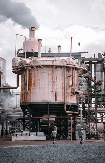
The failure mode to design against is simple: a 5 mm rock fragment or a torn wiper that passes a missing screen will clog a DAF micro-bubble nozzle and shut down 300 m³/h of treatment capacity. The fix is also simple — and cheap. A rotary mechanical bar screen with continuous-duty stainless rake teeth, dual overload protection, and a self-cleaning brush discharge runs unattended and protects several hundred thousand dollars of downstream equipment.
For raw pit water, specify a coarse bar spacing of 3–10 mm as the primary barrier. If rock fines or abrasion are significant, add a finer 1–3 mm secondary screen immediately ahead of the DAF to keep the bubble diffuser clear. On most sites this $10,000–$30,000 piece of equipment is the single best ROI decision in the entire process train — it pays for itself the first time it spares a pump or a membrane module. The wider intake-protection strategy is part of the same discipline covered in 2026 mining pretreatment limits in the US.
Step 3 — Equalization, pH Correction and Chemical Conditioning
Pit dewatering flows vary 30–60% between shift cycles, pump cycling, and storm peaks, and any step downstream that needs a stable feed will punish that variability. A 4–8 hour hydraulic retention equalization basin is the lowest-cost insurance on the site: it dampens flow swings, allows suspended solids to settle passively, and gives the chemical dosing loop a stable influent to react to.
pH correction sits at the front of the basin outlet. AMD-affected water typically requires lime or NaOH dosing to 6.5–8.5 before biological or membrane steps; outside that band, MBR biology collapses, coagulant demand spikes, and RO membranes foul faster. Run the conditioning loop on a PLC-controlled automatic chemical dosing system for coagulant, flocculant and pH adjusters, skid-mounted and factory-tested for fast deployment. The integrated water purification skid packages the equalization, reaction and clarification stages into a single pre-engineered unit for greenfield sites.
The mass-balance discipline is not theoretical. Colorado water-augmentation plans quantify the consumptive use of community wastewater by the number and type of sewage systems, with soil-absorption systems credited as a 10% diversion and evapotranspiration units treated as 100% diversions (ASABE, 2001). Apply the same accounting to a mine: every litre of acid mine drainage, every kilogram of coagulant, every cubic metre of reuse has to balance against the discharge and the receiving environment, and the chemical dosing budget falls out of that ledger.
Step 4 — DAF or Lamella Clarification for TSS and FOG Removal
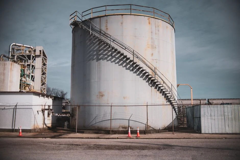
DAF is the default for high-TDS, oily, or colloidal feed where micro-bubble flotation in the 4–300 m³/h range achieves 80–95% TSS removal in a compact footprint. A dissolved air flotation system handles the harder streams — feed oil/grease above 50 mg/L, turbidity spikes above 1,000 NTU, or colloidal fines that defeat gravity settling. The lamella clarifier is the lower-energy alternative for settledable solids: 20–40 m/h surface loading rates, no saturation tank, and chemical savings up to 30% when oil and grease are not a concern. A high-efficiency sedimentation tank configured as a lamella clarifier is the right pick for clear pit water with low organics.
The decision rule is straightforward. If feed oil/grease exceeds 50 mg/L or feed turbidity spikes above 1,000 NTU, specify DAF first. Otherwise, a lamella clarifier delivers the lowest 10-year OPEX. With the integrated purifier pre-polishing 3,000 mg/L raw surface water to under 3 mg/L, the DAF can be reserved for the harder stream and run at design loading. The side-by-side comparison is in the table below; a deeper DAF-vs-clarifier cost analysis is in DAF vs clarifier for mining wastewater in 2026.
| Parameter | DAF | Lamella Clarifier |
|---|---|---|
| Flow range per unit | 4–300 m³/h | 20–40 m³/h surface loading |
| Best feed TSS | 200–5,000 mg/L, colloidal, oily | 200–1,500 mg/L, settleable |
| TSS removal | 80–95% | 60–85% |
| Oil/grease limit | Handles >50 mg/L | Not designed for free oil |
| Footprint | Compact, small area | Larger, tall slab |
| Energy | Saturation pump + recycle | No recycle, lowest energy |
| Chemical use | Coagulant + flocculant baseline | Up to 30% lower chemical use |
| 10-year OPEX profile | Higher energy, higher recovery | Lowest OPEX on benign water |
Step 5 — Biological Polishing and MBR Membrane Filtration
Conventional activated sludge needs a separate clarifier and discharges 20–30 mg/L TSS — often too high for haul-road dust suppression and well above what a downstream RO can tolerate. An integrated MBR membrane bioreactor system collapses the aeration tank and the solids-separation step into one vessel, drops TSS to under 1 mg/L, and shrinks the footprint by roughly 60%.
Specify the DF-series 0.1 μm PVDF flat-sheet MBR module with an integrated aeration box for continuous scouring, individually replaceable elements, and a flux density that delivers 80–225 m² of membrane area per cassette — producing 32–135 m³/day per unit at 10–20× lower energy than an external cross-flow system. The sizing math: a 1,000 m³/day mine water stream needs roughly 8–12 DF modules in a single MBR train, sized to leave 30% spare capacity for peak storm events and maintenance windows.
MBR permeate is suitable for haul-road dust suppression, equipment washdown, and as a stable feed to RO if higher-purity reuse is required. The modular sizing and parameter envelope is in the table below; the compliance angle is covered in BHP mine wastewater treatment in 2026.
| Parameter | Value / Range |
|---|---|
| Membrane material | PVDF, 0.1 μm nominal pore |
| Module configuration | Flat-sheet cassette, replaceable elements |
| Membrane area per unit | 80–225 m² |
| Permeate flow per unit | 32–135 m³/day |
| Effluent TSS | <1 mg/L (vs 20–30 mg/L conventional) |
| Footprint vs CAS | ~60% smaller |
| Energy vs cross-flow MBR | 10–20× lower |
| Modules per 1,000 m³/day train | 8–12 (with 30% spare) |
| Reuse outlets | Dust suppression, washdown, RO feed |
Step 6 — Sludge Dewatering With a Plate-and-Frame Filter Press
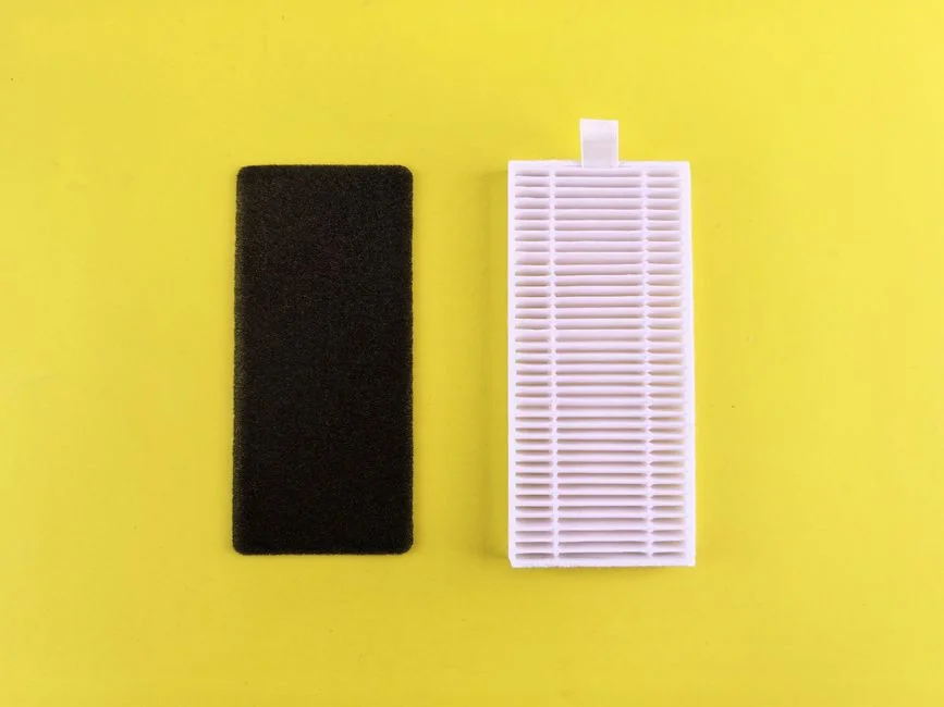
DAF float and MBR waste activated sludge arrive at 1–3% solids — a liquid-hauling liability that compounds over a 15-year LOM. The fix is mechanical dewatering on a plate-and-frame filter press with a filtration area from 1 m² to 500 m² and a configuration from manual through hydraulic to PLC-automatic, sized to the daily sludge volume.
Performance is well understood: cake solids of 25–35% cut sludge mass by 80–90% and produce a stackable cake that is landfill-ready or suitable for backfill. On a 19,440 m³/day evaporation-class site, every 1% reduction in hauled water saves tens of millions of dollars over the LOM (Minetek, 2025-08). Translate that to the cake: pressing 1,000 m³/day of waste activated sludge from 2% to 30% removes roughly 280 m³/day of water that would otherwise be trucked — and at remote mine sites, truck-and-tip is the dominant OPEX line for the solids stream.
Filtrate from the press returns to the head of the equalization basin for retreatment, and the cake is the only net solid leaving the plant. On a cost-per-cubic-metre-of-cake basis, plate-and-frame presses consistently beat decanter centrifuges and belt presses on duty cycle, polymer consumption, and the dryness of the final cake.
Step 7 — Reuse, Mechanical Evaporation and ZLD Compliance
Reuse comes first because it is the cheapest disposal path. MBR permeate is suitable for haul-road dust suppression, equipment washdown, and irrigation; polishing a slipstream through an industrial RO system delivers boiler-feed or process-water quality. A small UV stage, such as the UV sterilizer water treatment unit, finishes the reuse loop for any worker-contact application.
For the residual brine stream that no membrane can process economically, mechanical evaporation is the cost leader. A 600/300-class unit evaporates up to 135 m³/h and handles high-TDS brine without the scaling risk that shuts down an evaporative crystallizer (Minetek, 2025-08). Three units running at 50% efficiency evaporate 4.86 ML per day — equivalent to an average-sized treatment facility — and twelve units deliver 19,440 m³/day, comfortably above the 12,000 m³/day site target. The cost math holds: ~$0.20/m³ for evaporation versus >$2.00/m³ for an equivalent treatment volume (Minetek, 2025-08).
ZLD compliance is non-negotiable: strict AMD and storm-runoff control, real-time groundwater and soil monitoring, and zero discharge to surface water, with large fines and shutdowns for breach (Minetek, 2025-08). The hybrid strategy — Steps 1–6 plus a small evaporation fleet — meets the obligation at roughly 20% of the cost of building a pure-treatment plant for the whole stream, and leaves only a small concentrated residual for the closure-phase treatment plant. The broader market trajectory is in ZLD adoption outlook 2026.
2026 Cost Framework: Build the Right Train for Your Site
The seven steps translate into two named scenarios that a procurement manager can defend to a board. The 'lean ZLD' path runs Steps 1–6 plus mechanical evaporation on the residual brine, blended cost approximately $0.40–$0.60/m³ depending on feed TDS, oil/grease, and electricity. The 'pure treatment' path runs Steps 1–6 plus RO polishing, blended cost approximately $1.50–$2.50/m³. Lean ZLD hits the Minetek 20%-of-pure-treatment benchmark and reserves a small RO train for the highest-quality reuse demand (Minetek, 2025-08).
Controllable CAPEX drivers are the four you should isolate in any board paper: hydraulic conductivity (which sets well density and pump CAPEX), feed turbidity (which sets clarifier sizing and polymer consumption), oil/grease (which forces DAF over lamella and adds saturation-pump CAPEX), and the ZLD deadline (which decides whether you finish on evaporation or escalate to crystallization). OPEX drivers follow the same axis plus energy tariff, polymer cost, and cake-disposal logistics.
Use the table below as the procurement short-list, then run the five-item selection checklist on the right before sign-off: (1) design flow rate in m³/day, (2) influent TDS in mg/L, (3) ZLD deadline year, (4) reuse demand by quality tier, (5) land/footprint constraint in m².
| Scenario | Process train | Blended cost ($/m³) | Best fit |
|---|---|---|---|
| Lean ZLD | Steps 1–6 + mechanical evaporation on residual | ~$0.40–$0.60 | Remote sites, 12,000 m³/day+ flow, tight ZLD deadline, minimal reuse demand beyond dust suppression |
| Pure treatment | Steps 1–6 + RO polishing | ~$1.50–$2.50 | Brownfield sites with high boiler-feed or process-water demand, lower flow, tight discharge consent |
| Hybrid | Steps 1–6 + small RO slipstream + evaporation on RO reject | ~$0.80–$1.20 | Mixed reuse demand, moderate flow, balanced CAPEX/OPEX target |
Frequently Asked Questions
What are the seven steps in a low-cost mine site wastewater treatment process train?
The seven steps are: (1) pit and groundwater dewatering, (2) coarse screening, (3) equalization and pH control, (4) DAF or lamella clarification, (5) MBR biological polishing, (6) sludge dewatering with a plate-and-frame filter press, and (7) reuse or mechanical evaporation for ZLD compliance.
How much does mechanical evaporation cost versus a full treatment plant on a mine site?
Reference data from Minetek (2025-08) puts mechanical evaporation at approximately $0.20 per cubic metre, including installation, additives, power, labour and maintenance, versus more than $2.00 per cubic metre for an equivalent water treatment facility — a 70–80% lower-cost finishing step.
When should a mine specify DAF instead of a lamella clarifier?
Specify DAF when feed oil/grease exceeds 50 mg/L or feed turbidity spikes above 1,000 NTU; otherwise a lamella clarifier delivers up to 30% lower chemical use and the lowest 10-year OPEX on benign water. Pair the DAF with a downstream integrated MBR system for the high-TDS, oily stream.