Why the Clarifier Is the Choke Point in a Municipal Plant
A wastewater clarifier is the threshold between a treatment plant that runs predictably and one that chokes on its own solids inventory (per S4). When gravity settling fails to produce a clean overflow and a dense underflow, every downstream stage — aeration, filtration, disinfection — loses its operating window. The clarifier is where biology ends and hydraulics takes over, and in 2026 the most common cause of an unplanned plant shutdown is not a failed blower or a torn membrane; it is a clarifier that has lost its sludge blanket during a wet-weather peak.
Two hydraulic conditions control performance in any sedimentation tank: the particle settling velocity must consistently exceed the upward liquid velocity created by the tank's overflow rate. When those numbers invert — which routinely happens during a 2.5–3x peak wet-weather surge — solids carry over the effluent launder and downstream filters load up in minutes. In a continuously fed tank, particles sort into four settling zones; Type I (discrete particle settling) dominates in primary clarifiers, and Type III (zone settling) is the regime inside secondary clarifiers where biological floc blankets form (per S4).
The 2026 A2O field study from Shahid Sadoughi University makes the gatekeeper role concrete: final effluent after the secondary clarifier measured 0.22 ± 0.05 mg/L LAS, 13.18 ± 3.7 mg/L NO₃-N, and 4.46 ± 0.18 mg/L TP over a 12-month sampling campaign (S2, 2026-04). Those numbers are not abstract — they are the actual discharge quality a secondary clarifier must hand to disinfection or reuse, and they prove that the clarifier is the single unit operation standing between permit compliance and a violation notice.
Primary vs Secondary vs Tertiary: Stage Drives Clarifier Choice
Clarifiers appear at two distinct points in a conventional activated-sludge plant, and confusing the two is the most common specification miss (per S4). Primary units receive raw sewage after screens and grit removal; secondary units receive mixed liquor from the aeration basin. The solids type, loading, and required effluent quality are different, so the tank hydraulic design and mechanical hardware must match the stage — not the available footprint.
| Parameter | Primary Clarifier | Secondary Clarifier | Tertiary Clarifier / Lamella |
|---|---|---|---|
| Influent | Raw sewage after screens/grit | Mixed liquor from aeration | Secondary effluent |
| Solids type | Dense inorganic/organic (sand, grit remnants, fecal matter) | Light, buoyant biological floc (high water content) | Residual TSS, chemical precipitate |
| Typical HRT | 1.5–2.5 h | 2–3 h | 0.25–0.5 h (lamella) |
| Target SOR (avg flow) | 30–50 m³/m²·day | 20–30 m³/m²·day | 60–120 m³/m²·day equivalent (plate area) |
| Sidewater depth | 3.0–4.0 m | 3.5–5.0 m | Plate spacing 50–80 mm at 45–60° |
| Sludge output | Primary sludge to thickener/digester | RAS returned, WAS wasted | Chemical sludge to dewatering |
| Typical effluent | 30–40% BOD removed upstream | <30 mg/L BOD/TSS (permit-dependent) | <5 mg/L TSS, <0.5 mg/L TP with chemical P |
The primary clarifier takes the first swing at suspended solids and organics, removing 30–40% of the BOD load before aeration and pulling dense grit remnants and floatable grease out of the train (per S4). Sludge hoppers and scum skimmers run in parallel, and the sludge removal mechanism must tolerate abrasive grit wear. The secondary clarifier does double duty: produce effluent clean enough for discharge or filtration, and reliably thicken settled activated sludge for return (RAS) or wasting (WAS). Biological floc is fragile — high turbulence or a fast scraper can shatter floc into pin particles that wash over the weir — which is why secondary units are designed deeper (3.5–5 m SWD) and at conservative SOR. The tertiary clarifier, increasingly a high-rate lamella or ballasted floc unit, targets residual TSS and phosphorus before disinfection or reuse. With alum, ferric chloride, or PACl dosed upstream, tertiary units routinely drive TP below 0.5 mg/L — a level the 4.46 mg/L A2O secondary effluent (S2) cannot meet on its own.
Circular, Rectangular, and Lamella: Geometry Comparison
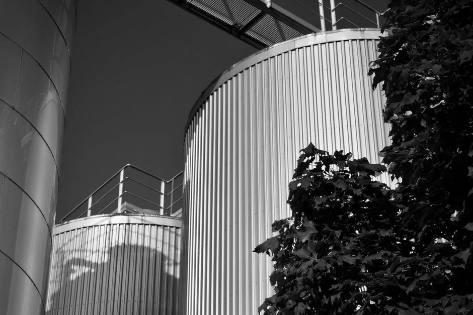
Three physical geometries cover the majority of municipal clarifier installations (per S4). The right shape is driven less by tradition and more by available footprint, sludge characteristics, and the cost of civil construction. The following matrix is the data you can lift directly into a design memo or review-board package.
| Parameter | Circular | Rectangular | Lamella / Inclined-Plate |
|---|---|---|---|
| Typical size | 15–60 m diameter | 3–6 m wide, up to 90 m long | Plates at 45–60° in compact basin |
| SOR (m³/m²·day) | 25–40 (primary), 20–30 (secondary) | 25–40 (primary), 20–30 (secondary) | 20–40 m/h equivalent loading on plate area |
| Footprint vs conventional | 1x (baseline) | 1x (baseline) | ~0.1x (10x smaller) |
| Sidewater depth | 3.0–5.0 m | 3.0–4.5 m | Plate stack height 1.0–2.5 m |
| Mechanical hardware | Center column drive, rotating scraper arms | Chain-and-flight or traveling bridge | Gravity hopper or screw auger; minimal moving parts |
| CAPEX | High (large concrete basin, torque-loaded drive) | Medium (shared walls reduce concrete volume) | Low–medium equipment cost; civil work small |
| OPEX / chemical demand | Standard | Standard | Up to 30% lower coagulant use vs conventional |
| Primary O&M risk | Drive torque spikes, radial short-circuiting if inlet baffle undersized | Chain tension/wear; snapped flight drops into basin | Plate scaling; sensitive to upstream floc quality; periodic acid CIP |
| Best fit | Large municipal secondary, square footprint available | Long narrow site, multiple parallel units, shared-wall construction | Retrofit capacity boost, industrial pretreatment, chemical-limited OPEX |
Circular clarifiers scale easily to 60 m diameter and dominate large municipal secondary duty, but the radial flow pattern can short-circuit if the inlet baffle or stilling well is undersized (per S4). Rectangular basins leverage shared-wall construction and run multiple units side by side on a constrained site, but the chain-and-flight collector is the chronic weak point — operators track flight alignment, sprocket tooth condition, and tensioner position weekly. The HydropureWater high-efficiency lamella clarifier is a representative inclined-plate unit: it stacks sludge recirculation, flocculation, and inclined-plate settling in a single vessel, runs at 20–40 m/h surface loading, and is documented to cut coagulant demand by up to 30% versus a conventional basin of equal throughput (HydropureWater product data, 2026). For an existing plant with a chemical-cost problem, that 30% is the line item that justifies the retrofit on a 10-year cost-of-ownership basis.
Sizing Rules That Actually Decide the Spec
Four numbers drive the tank geometry, drive torque, and sludge removal capacity; the rest of the spec follows from them.
Surface overflow rate (SOR) is the master design parameter. Hold to 30–50 m³/m²·day for primary clarifiers and 20–30 m³/m²·day for secondary at average flow; anything above those numbers turns the effluent launder into a solids bypass (per S4). For sizing under wet-weather peaks, apply a peak factor of 2.5–3x average flow and recheck SOR at peak — many plants are SOR-noncompliant for 20–30% of the year without realizing it.
Sidewater depth on the secondary should be 3.5–5 m. That depth gives the floc a quiet settling column and protects against hydraulic surges that would otherwise pull pin floc over the weir. Sludge blanket control targets a 0.3–0.9 m interface depth, and modern installations tie RAS pump speed directly to blanket-level sensors so the interface stays put under variable flow (per S4). A blanket that drifts toward 1.0 m and approaches the weirs is a clarifier about to fail.
Hydraulic retention time runs 1.5–2.5 h primary and 2–3 h secondary. Coagulant and polymer selection must be jar-test verified against the plant's actual mixing energy and detention time; well-formed flocs settle 2–5x faster than untreated colloids (per S4), which is why a properly tuned HydropureWater automatic chemical dosing system is rarely an optional accessory — it is the unit operation that decides whether the rest of the clarifier hits its design SOR or wastes chemical spend without improving capture.
2026 Selection Criteria: What Has Changed
Four pressure vectors are reshaping clarifier selection in 2026, and they are converging fast enough that a spec written in 2022 is already out of date.
| 2026 Driver | Impact on Clarifier Choice | Quantified Lever |
|---|---|---|
| Tighter effluent P/N limits | Tertiary lamella or ballasted floc now mainstream in municipal trains | A2O secondary effluent at 4.46 mg/L TP (S2, 2026) cannot meet <0.5 mg/L reuse TP without chemical P polishing |
| Wet-weather peak resilience | Deeper SWD, blanket-level control, peak factor 2.5–3x | Blanket rise to 0.9–1.0 m triggers effluent solids loss |
| Energy & chemical cost | Favors lamella retrofits and tighter jar-test programs | Up to 30% lower coagulant use on HydropureWater lamella units (HydropureWater product data, 2026) |
| MBR/UF primary effluent | Shifts primary duty toward sludge thickening, away from BOD/TSS removal | UF at 0.03 µm PVDF cutoff changes upstream load envelope |
First, tighter phosphorus and nitrogen discharge limits are pushing tertiary lamella and ballasted floc units into mainstream municipal use rather than industrial-only retrofits. The 2026 A2O field data is the smoking gun: secondary clarifier effluent at 4.46 mg/L TP and 13.18 mg/L NO₃-N (S2) is above the reuse and many surface-discharge permits in effect today, so tertiary polishing is no longer optional. Second, climate-driven wet-weather peaks are forcing plants to size for peak factor 2.5–3x average, which favors deeper sidewater depth and active sludge blanket control rather than passive overflow weirs. Third, chemical and energy cost pressure makes the 30% lower coagulant consumption of a lamella retrofit a real 2026 OPEX line item, not a brochure claim. Fourth, plants pairing a HydropureWater hollow-fiber ultrafiltration system downstream are changing primary clarifier duty: with UF cutting particulates at the 0.03 µm PVDF pore size, the primary unit is increasingly specified for sludge thickening rather than raw BOD reduction. For more on that downstream decision, see the disc filter tertiary treatment buyer's guide and the MBR vs conventional activated sludge comparison.
Decision Framework: Which Clarifier Should You Specify?
Use the following one-glance rule to shortlist geometry before detailed sizing: greenfield municipal secondary with square footprint available → circular, 15–60 m diameter, 3.5–5 m SWD. Long narrow site or multiple parallel units with shared-wall construction → rectangular with chain-and-flight. Existing plant needing a capacity boost or a chemical-OPEX reduction → lamella retrofit. If the downstream stage is MBR or UF, relax the secondary SOR target and shift the clarifier duty toward sludge thickening — the membrane is now your effluent quality gatekeeper. For an industrial train where the question is DAF versus sedimentation, the DAF vs clarifier decision guide for industrial plants walks through the same logic for a non-municipal flow sheet.
Frequently Asked Questions
What is the best clarifier type for a municipal wastewater treatment plant?
The best clarifier type is stage-specific: rectangular or circular primary clarifiers at SOR 30–50 m³/m²·day for raw-settable removal, circular secondary clarifiers at SOR 20–30 m³/m²·day and 3.5–5 m sidewater depth for activated-sludge separation, and lamella or inclined-plate units as a high-rate tertiary retrofit when footprint or chemical OPEX is the constraint.
What surface overflow rate (SOR) should I use for a primary vs secondary clarifier?
Use 30–50 m³/m²·day for primary clarifiers and 20–30 m³/m²·day for secondary clarifiers at average flow (per S4). Recheck at your design peak wet-weather factor; SOR noncompliance during a 2.5–3x peak event is the most common cause of secondary clarifier failure.
Can a lamella clarifier replace a circular secondary clarifier in a municipal plant?
Yes, but with caveats. A lamella unit delivers equivalent SOR in roughly 10% of the footprint and cuts coagulant use by up to 30%, but it is sensitive to upstream floc quality and requires periodic acid cleaning to control plate scaling. It is most often specified as a tertiary polishing or retrofit capacity booster rather than a full primary-secondary replacement.
How does the 2026 A2O field data change clarifier selection?
The 2026 A2O study reported secondary clarifier effluent at 4.46 mg/L TP, 13.18 mg/L NO₃-N, and 0.22 mg/L LAS (S2, 2026-04). Because those values exceed tightened 2026 reuse and discharge limits for phosphorus and nitrate, tertiary polishing — typically a lamella or ballasted floc unit with chemical P precipitation — is no longer optional in trains targeting reuse or strict surface-water permits.
What sidewater depth should a secondary clarifier have for activated sludge?
Specify 3.5–5 m sidewater depth for a secondary clarifier handling activated-sludge mixed liquor (per S4). Deeper SWD gives the biological floc a quiet settling column, protects against hydraulic surges, and pairs with a 0.3–0.9 m sludge blanket target controlled by RAS pump speed tied to blanket-level sensors.