

Why Helsinki fabs and data halls need a four-stream wastewater logic in 2026
Helsinki semiconductor fabs and data halls in 2026 should segregate process wastewater into four streams — CMP slurry, HF/fluoride spent etch, IPA/NMP solvent rinse, and cooling-tower blowdown — treat each on a dedicated train, and run the cooling-blowdown loop through softening plus RO at up to 95% recovery for tower make-up reuse. Compliance sits with HSY trade-waste rules for sewer discharge and an AVI/ELY environmental permit under the Ympäristönsuojelulaki 527/2014 for any release above trigger concentrations, with EU Industrial Emissions Directive 2010/75/EU applying to larger fabs.
The volume pressure behind that segregation logic is real. The global semiconductor market reached US$543.1 billion in 2021 (SIA, 2022, cited in the 2024 semiconductor wastewater review) and Korea alone reported a 177,937 m³/d (19.3%) jump in fab wastewater discharge between 2010 and 2019 (Statistics Korea, cited in the same review). Helsinki's industrial catchment now carries both hyperscale data-hall cooling-blowdown loads — Helen's heat-reuse project captures excess heat from Equinix's Helsinki data centres to warm local homes (S2) — and inland fab or back-end packaging capacity, so CMP, HF, solvent, and cooling streams co-exist in the same HSY trade-waste catchment and cannot be mixed without over-sizing every downstream unit operation.
Mixed-stream treatment forces oversized chemical precipitation, oversized biological reactors, and membrane fouling that pretreatment alone cannot recover from. Finland's permitting logic is stream- and parameter-specific, so segregation is also a compliance prerequisite, not just a cost choice. For a peer designing a 2026 package, the four-stream logic is the answer a Finnish design-review panel will accept first; chemistry optimisation is the second conversation. The same logic underpins the broader semiconductor ultrapure water treatment guide, where UPW reclaim loops and wastewater trains are co-engineered rather than treated as separate utilities.
The 2026 Helsinki regulatory stack for fab and data-hall wastewater
A 2026 Helsinki wastewater design package must clear three overlapping authorities before a single cubic metre can leave the site. The first is HSY (Helsinki Region Environmental Services) viemäri trade-waste rules, which govern every discharge into the sewer, including fluoride, heavy metals, temperature, pH, and flow limits on the issued consent. The second is an AVI/ELY environmental permit (ympäristölupa) under Ympäristönsuojelulaki 527/2014, which is required for any release above the statute's trigger concentrations — fluoride above 10 mg/L at the point of release, or volumes above the trade-waste agreement threshold, are common triggers for fab process streams. The third is the EU Industrial Emissions Directive 2010/75/EU, which catches larger fabs and sets BAT-AEL ranges for wastewater parameters and operator monitoring obligations.
Two Helsinki-specific design implications follow. The Hamina seawater-cooling paradigm — Google draws cooling water from the Bay of Finland at its Hamina site (S4) — shifts the cooling-water mass balance and means inland Helsinki fabs cannot assume the same free-cooling source. They must plan for higher reuse on the cooling-tower blowdown loop. Second, the cost of retrofitting segregation after construction is several multiples higher than building it in at the pipe-rack stage, which is why PFAS in CMP slurries and NMP in the solvent stream should be designed for now, even where no hard Finnish discharge limit yet exists. This regulatory layering is what differentiates a Finnish permit path from a generic EU design; the same logic shows up in the parallel Vancouver fab and data-hall guide and the Toronto fab and data-hall guide.
| Authority | Instrument | Typical trigger / scope | Design implication |
|---|---|---|---|
| HSY (Helsinki Region Environmental Services) | Viemäri trade-waste consent | Every sewer connection; fluoride, heavy metals, pH, temperature, flow | Define final discharge envelope per stream; size equalisation to absorb batch spikes |
| AVI / ELY Centre | Ympäristölupa under Ympäristönsuojelulaki 527/2014 | Release above trigger concentrations (e.g. F⁻ > 10 mg/L) or above volume threshold | Segregate fluoride, solvent, and metals streams; document each train's compliance path |
| EU IED 2010/75/EU | BAT-AEL ranges, operator monitoring | Larger fabs above IED capacity thresholds | Specify continuous monitoring on common discharge header; align with BAT conclusions |
| Emerging — PFAS / NMP | EU solvents guidance, PFAS restriction trajectory | CMP slurries, solvent rinses | Build segregation in at the pipe-rack stage; retrofit cost is several multiples higher |
CMP slurry train: lamella clarification plus 0.03 µm PVDF ultrafiltration
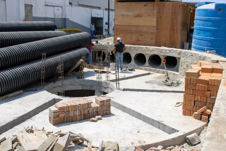
A defensible CMP train for a 2026 Helsinki fab starts with dedicated equalisation, runs through lamella clarification, and finishes on 0.03 µm PVDF ultrafiltration for a particulate-free bleed. The influent envelope is colloidal silica or ceria residue, low TDS, TSS 200–1,000 mg/L, and pH 8–11. Equalise in a dedicated tank with 24–48 h residence to absorb CMP batch swings, trim pH to 9.5–10.5 with a PLC-controlled chemical dosing skid, and send the flow to a lamella clarifier at 20–40 m/h surface loading; lamella geometry cuts coagulant demand by roughly 30% versus a conventional clarifier (HydropureWater 2026 equipment specifications). Clarifier overflow passes through 0.03 µm PVDF ultrafiltration accepting feed turbidity up to 300 NTU, at 50–80 LMH flux, producing a permeate suitable for RO polish or direct reuse in non-process rinses.
Solids handling is part of the design, not an afterthought. UF backwash solids go to a plate-and-frame filter press for dewatering to 25–35% dry solids for off-site disposal. The upstream clarifier can be a high-efficiency sedimentation tank sized for the lamella surface-loading rate. This train keeps the slurry stream isolated from the fluoride and solvent streams, which is the only way to avoid forcing the downstream membranes to handle silica plus CaF₂ plus solvent — a fouling combination that no chemical program can reliably clean.
| Stage | Equipment / setpoint | Influent | Effluent target |
|---|---|---|---|
| Equalisation | Dedicated tank, 24–48 h residence, pH 9.5–10.5 | TSS 200–1,000 mg/L, pH 8–11 | Buffered feed to clarifier |
| Clarification | Lamella, 20–40 m/h surface loading | Equalised slurry | Low-TSS overflow (< ~100 mg/L) |
| UF polish | 0.03 µm PVDF, 50–80 LMH, feed turbidity up to 300 NTU | Clarifier overflow | Particulate-free bleed for RO or non-process rinse |
| Solids | Plate-and-frame filter press | UF backwash | 25–35% dry solids, off-site disposal |
HF and fluoride spent-etch train: CaCl₂ precipitation plus RO polish
The fluoride train is the one a Finnish design-review panel will scrutinise first, because fluoride is the trigger parameter that pushes a project from an HSY trade-waste consent alone into AVI/ELY permitting territory. Influent runs F⁻ 100–5,000 mg/L at low pH, often co-contaminated with nitric or sulphuric acids. Dose CaCl₂ at 1.5–2.0× stoichiometric fluoride in an agitated reactor with 30–60 min residence, flocculate with anionic polymer, settle in a lamella clarifier, then pass supernatant through a multi-media filter to bring SDI below 3.
Polishing is handled by an industrial RO system at 75–85% recovery on fluoride feed, which is held below the 95% ceiling to protect membranes from CaF₂ scaling carryover; the brine returns to the precipitation reactor to recover residual reagent. The MMF upstream of RO is the right place to install a dedicated multi-media filter for consistent SDI reduction. Effluent target is <10 mg/L F⁻ to the HSY sewer; CaF₂ sludge is dewatered to 25–35% dry solids on a plate-and-frame filter press and consigned off-site. The CaCl₂ dose stoichiometry is the parameter the reviewer will want to see in the mass balance — 1.5–2.0× stoichiometric is the band where pH, residual fluoride, and sludge yield balance out across the operating range.
| Stage | Equipment / setpoint | Influent | Effluent target |
|---|---|---|---|
| Equalisation + acid neutralisation | Agitated tank | F⁻ 100–5,000 mg/L, low pH | Buffered feed for precipitation |
| CaCl₂ precipitation | 1.5–2.0× stoichiometric, 30–60 min residence | Neutralised fluoride | Low-F⁻ supernatant + CaF₂ sludge |
| Clarification | Lamella clarifier | Precipitation effluent | Low-TSS overflow to MMF |
| MMF | Multi-media filter, SDI < 3 | Clarifier overflow | RO feed quality |
| RO polish | 75–85% recovery on fluoride feed; brine recycle | MMF filtrate | <10 mg/L F⁻ to HSY sewer |
| Solids | Plate-and-frame filter press | CaF₂ sludge | 25–35% dry solids, off-site disposal |
IPA and NMP solvent-rinse train: DAF pre-skim plus membrane bioreactor
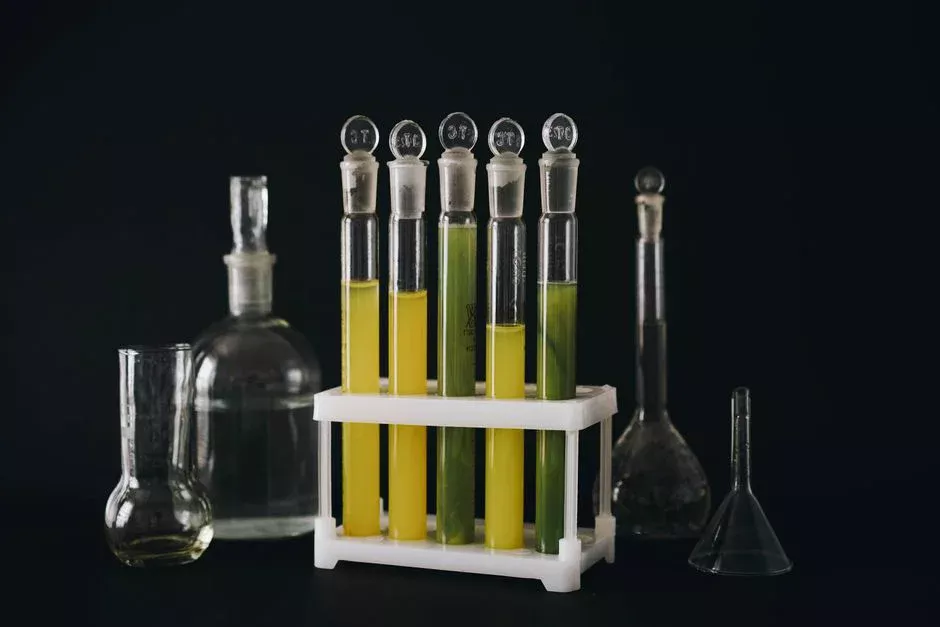
The solvent stream is the highest design risk in a 2026 Nordic fab, because IPA and NMP cannot be co-mingled with fluoride or metal-bearing streams without forcing the entire train to handle COD loads of 5,000–20,000 mg/L. Segregate it, and the rest of the plant can run smaller and cleaner. Influent COD typically sits in the 5,000–20,000 mg/L band with a floatable solvent load that defeats mixed-stream biological treatment. The first unit operation is a dissolved air flotation unit (4–300 m³/h) to skim floatable solvent, followed by equalisation, then an MBR membrane bioreactor at MLSS 8,000–12,000 mg/L producing effluent turbidity below 1 NTU. MBR footprint is roughly 60% smaller than an equivalent conventional activated-sludge system for this COD load (HydropureWater 2026 equipment specifications).
Final polish is UV or ClO₂ before HSY sewer discharge or tool-rinse reuse. NMP discharge limits are tightening in step with EU solvents guidance, so designing for segregation now — rather than waiting for a permit revision — keeps the retrofit cost off the capex line. For a designer, the practical take-away is that the solvent train should be the first stream pinned down in the P&ID, because every downstream tie-in depends on it staying isolated.
Data-hall cooling-tower blowdown train: softening, RO and UV for make-up reuse
Helsinki's heat-reuse story (S2) and the Hamina seawater-cooling example (S4) make the cooling-tower blowdown loop the most site-specific train in the design package. Inland Helsinki data halls cannot copy Hamina's Bay of Finland seawater source directly, so the blowdown stream is designed for cooling-tower make-up reuse rather than sewer discharge. Influent at 4–6 cycles of concentration runs conductivity 2,500–4,500 µS/cm, SiO₂ 80–150 mg/L, and hardness 400–800 mg/L as CaCO₃. The treatment sequence is lime softening to Ca²⁺ below 50 mg/L as CaCO₃ via an industrial water softener, multi-media filtration for SDI reduction, RO at up to 95% recovery, and a UV steriliser at 40 mJ/cm² for cryptosporidium and giardia control on the reuse stream.
Mass balance: permeate returns to the cooling-tower basin; the 5% brine goes to a side-stream RO at 50% recovery, producing roughly 7–8 m³/day of final brine from a 150 m³/day inflow — usually below the threshold where a thermal ZLD step pays back in Helsinki tariff conditions. For coastal sites, the Hamina model shows that siting and water-source choice can shift the whole blowdown balance; inland Helsinki data halls should plan for higher reuse and a softening + RO loop rather than free seawater cooling.
| Stage | Equipment / setpoint | Influent | Effluent target |
|---|---|---|---|
| Softening | Lime softener, Ca²⁺ < 50 mg/L as CaCO₃ | 2,500–4,500 µS/cm, 400–800 mg/L hardness | Softened blowdown |
| MMF | Multi-media filter, SDI reduction | Softened blowdown | RO feed quality |
| Primary RO | Up to 95% recovery | MMF filtrate | Permeate to cooling-tower basin |
| Side-stream RO | ~50% recovery on 5% brine | Primary RO reject | ~7–8 m³/day final brine at 150 m³/day inflow |
| UV polish | 40 mJ/cm² | RO permeate | Reuse-ready for tower make-up |
Reuse versus ZLD for Helsinki fabs in 2026: a decision framework
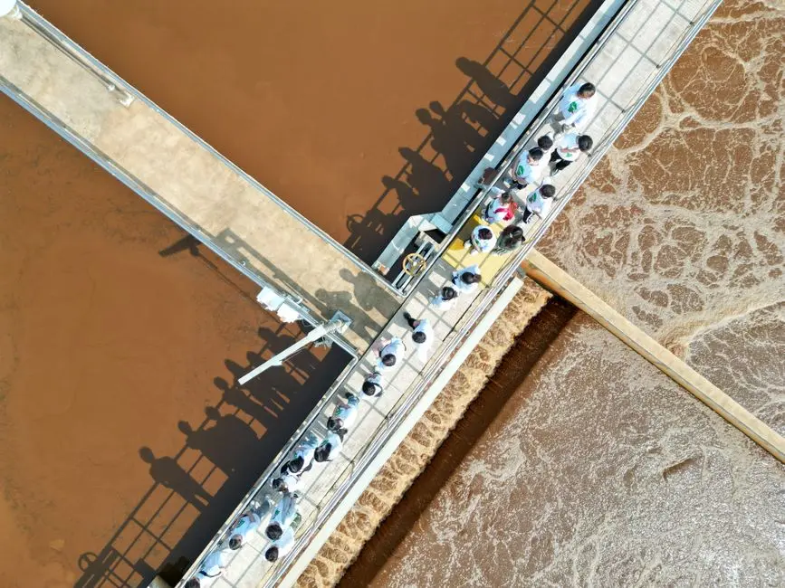
The reuse-versus-ZLD decision for a 2026 Helsinki fab is driven by sewer-acceptance cost, water tariff, and brine disposal options. RO + EDI reclaims 75–90% of fab rinse water; EDI stacks replace mixed-bed ion exchange and remove the acid/caustic regeneration loop, which matters where HSY is tightening trade-waste acceptance of regeneration waste (HydropureWater 2026 field data). PLC-controlled chemical dosing ties the RO + EDI loop to the analyser signals that drive both the HSY sewer and AVI/ELY permit limits from a single instrument set.
Thermal ZLD (crystalliser or brine concentrator plus thermal evaporator, with solid salt sent off-site) is the right answer only when sewer discharge is barred or brine disposal cost exceeds the thermal step's opex. Sensitivity to industrial potable-water and sewer tariffs in the Helsinki metro is the key driver — reuse above roughly 50 m³/day typically returns the RO + EDI capex inside 3–5 years on water-cost avoidance alone, but the exact figure must be verified against current HSY industrial water and sewer schedules before it is quoted in a design review. Helsinki-area industrial water and sewer tariffs are typically among the highest in the Nordics, which shifts the optimal point toward higher reuse rather than discharge.
Discharge limits and monitoring the 2026 Helsinki consent will set
A 2026 Helsinki consent will set numerical limits for the parameters listed in the regulatory section, with a flow-proportional sampler on the common discharge header and high-level alarms on each equalisation tank driving PLC-controlled shutdown (HydropureWater field data, 2026). The PLC-controlled chemical dosing skid should be designed to meet both HSY sewer and AVI/ELY permit limits from a single set of analyser signals — one analyser network, two compliance envelopes — so the operations team is not maintaining two independent trim loops.
Two emerging parameters deserve early design attention even where no hard Finnish limit yet exists: PFAS in CMP slurries and NMP in the solvent stream. EU and Nordic discharge schedules are tightening in step, and the cost of retrofitting segregation after construction is several multiples of building it in at the pipe-rack stage.
Frequently Asked Questions
Do Helsinki semiconductor fabs need an environmental permit for process wastewater in 2026?
Yes. Any release above the Ympäristönsuojelulaki 527/2014 trigger concentrations — for example fluoride above 10 mg/L at the point of release, or volumes above the trade-waste agreement threshold — requires an AVI/ELY ympäristölupa in addition to the HSY viemäri trade-waste agreement. Larger fabs are also caught by EU Industrial Emissions Directive 2010/75/EU, which adds BAT-AEL ranges and operator monitoring obligations.
What fluoride limit applies to sewer discharge in Helsinki?
Typical HSY trade-waste fluoride limit is below 10 mg/L at the point of discharge. The CaCl₂ precipitation + lamella clarification + multi-media filtration + RO train described above reliably meets this on feeds up to 5,000 mg/L F⁻, with RO recovery held at 75–85% to protect membranes from CaF₂ scaling carryover.
How should a hyperscale Helsinki data hall handle cooling-tower blowdown in 2026?
Treat for cooling-tower make-up reuse, not sewer discharge, via softening + multi-media filtration + RO at up to 95% recovery + UV at 40 mJ/cm². The 5% brine from a 150 m³/day inflow compresses to roughly 7–8 m³/day of final brine, which is usually below the threshold where a thermal ZLD step pays back in Helsinki tariff conditions.
Which wastewater stream carries the highest design risk in a 2026 fab?
The IPA/NMP solvent stream, because it cannot be mixed with fluoride or metal-bearing streams without forcing the whole train to handle 5,000–20,000 mg/L COD. Segregate it and run DAF + MBR, with UV or ClO₂ polish before sewer discharge or tool-rinse reuse.
Does the Hamina seawater-cooling model apply to inland Helsinki data halls?
No. Hamina uses Bay of Finland seawater for cooling (Google, S4); inland Helsinki sites should plan for higher reuse and a softening + RO blowdown loop rather than free seawater cooling. The mass balance, brine volume, and ZLD threshold all shift accordingly.