Why Indianapolis Chemical Plants Are Re-asking the DAF vs Clarifier Question in 2026
For Indianapolis chemical plants operating in 2026, dissolved air flotation (DAF) is the right primary clarifier when wastewater carries emulsified oils, FOG above ~200 mg/L, or precipitated heavy metals, because micro-bubble flotation reaches 80–95% TSS removal in 15–25 minutes. A lamella or circular clarifier remains the lower-CAPEX choice for chemical streams dominated by settleable inorganic solids and stable pH above IDEM 327 IAC 5 pretreatment limits.
Chemical manufacturers in Marion, Hendricks, Johnson, and Hamilton counties run a different mix than food processors or refineries. Their streams carry solvent emulsions from batch reactors, surfactant-bearing rinses, and metal-laden washwater — none of which behaves like the free oil in a poultry plant or the stable oil-in-water cut at a refinery desalter. The choice between adding a DAF skid, retrofitting a lamella clarifier, or rebuilding a circular clarifier therefore cannot be made on generic FOG logic; it must be defended against IDEM 327 IAC 5 categorical standards and the local sewer-use ordinances administered by the Belmont and Southport POTW districts, which cap FOG and metals at the discharge manhole.
What changed in 2026 is enforcement density. IDEM pretreatment inspections in Central Indiana are running more frequent sampling events, and the Belmont and Southport POTWs have tightened surcharge triggers for any single excursion on FOG, Cu, Ni, Zn, or hexavalent chromium. Plants that deferred primary-solids upgrades in 2023–2024 are now facing consent-order risk and looking at three paths: install a DAF, retrofit a clarifier with inclined plates, or rebuild the civil clarifier. Each path has different CAPEX bands, footprint impacts, and compliance timelines — and that trade-off is the subject of the broader 2026 ETP buyer's guide for industrial plants in this region.
How a DAF Actually Treats Chemical Wastewater
DAF separates suspended matter by attaching micro-bubbles to particles and floating them to the surface, where an automatic skimmer removes the float. A pressurized recycle stream — typically 10–30% of the treated flow — is saturated with air at 4–6 bar and then released into the contact zone, producing bubbles in the 10–80 μm range. Those bubbles attach to oil droplets, metal hydroxides, and colloidal TSS, lifting them in 3–5 minutes. Total hydraulic residence runs 15–25 minutes, and the float layer is removed continuously while clarified underflow exits at the bottom.
For chemical-plant flows in the 5–150 m³/h range typical of batch operations in Indianapolis, the HydropureWater DAF system covers 4–300 m³/h across 13 standard models with automatic skimming and a dedicated micro-bubble contact zone, allowing right-sizing without custom fabrication. The standard build is 304 stainless steel, which tolerates acidic rinse streams (pH 2–4), caustic clean-in-place residuals (pH 11–13), and chloride-bearing process water at ambient temperatures.
Independent evidence supports DAF as a robust chemical-stream pre-treatment step. Published pilot work on combining DAF with modified moving-bed biofilm reactors (MMBBR) for synthetic oily wastewater showed stable TSS and oil removal across shock loadings, confirming that DAF handles the variable influent characteristic of batch chemical production (per SSRN 4731382, 2024). Field experience with mobile DAF pilots in chemical and metal-precipitation service also shows that 304 stainless construction resists corrosion in chloride and acid-cleaning service (UCC Environmental DAF technical brief, 2026).
How a Clarifier Treats Chemical Wastewater
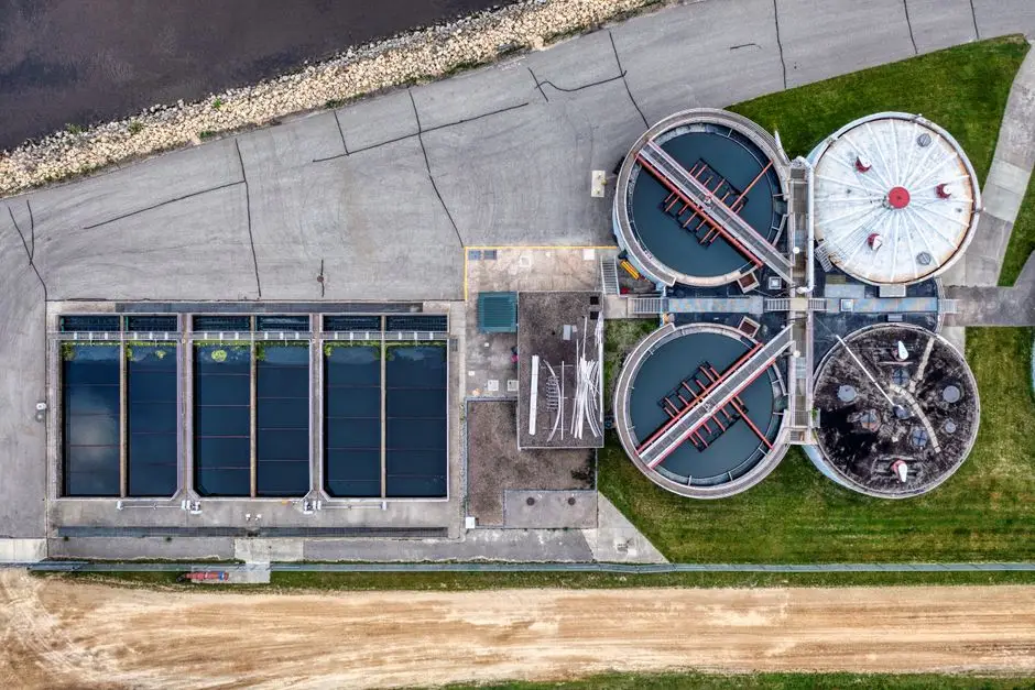
A conventional clarifier relies on gravity settling. Wastewater enters a center well, flows radially outward, and suspended solids drop to the bottom under a slow-moving rake. Hydraulic residence runs 1.5–3 hours, and surface loading sits at 1–3 m/h for a conventional circular basin. A lamella clarifier — such as the HydropureWater lamella clarifier — installs inclined plates at 55–60°, increasing effective surface area and pushing hydraulic loading to 20–40 m/h without expanding the basin footprint.
Clarifiers handle chemical streams well when the solids are dense, settleable, and chemically stable. A coordinated program that pairs flow-equalization basins with primary clarification and downstream coagulation can manage steady inorganic loads — the typical architecture for metals-precipitation and lime-sludge service (per ChemREADY Indianapolis/Fort Wayne process description, 2026). Polymer dose for a clarifier typically runs 0.5–3 mg/L of a high-molecular-weight flocculant, lower than DAF in absolute terms but more sensitive to mixing energy.
Clarifiers fail predictably on chemical streams that violate the settling assumption. Emulsified oils do not settle at any reasonable residence time. Low-density metal hydroxides — Al(OH)₃, Cr(OH)₃ — can resuspend under rake-induced turbulence. pH swings below 5 or above 10 destabilize floc and turn clarified overflow cloudy within minutes. A lamella retrofit helps when the basin is already in place and the solids are heavy inorganics: the plates multiply the effective area, but they do not change the underlying settling physics.
DAF vs Clarifier: Parameter-by-Parameter Comparison
The table below is built for a P&ID review: each row is a parameter an engineer must defend in a capital meeting. Values reflect typical operating ranges for chemical-plant service and the equipment documented in current vendor literature; treat them as order-of-magnitude engineering ranges, not guarantees.
| Parameter | DAF | Lamella / Circular Clarifier |
|---|---|---|
| TSS removal efficiency | 80–95% in 15–25 min | 50–85% in 1.5–3 h |
| FOG / oil removal | 85–98% (incl. emulsified) | 30–60% (free oil only) |
| Heavy-metal precipitate capture | Effective on colloidal hydroxides | Effective on dense hydroxides; poor on colloids |
| Hydraulic residence time | 15–25 minutes | 1.5–3 hours (circular); 30–60 min (lamella) |
| Surface loading rate | 15–25 m/h | 1–3 m/h (circular); 20–40 m/h (lamella) |
| Polymer demand | 5–20 mg/L | 0.5–3 mg/L (high-MW flocculant) |
| Footprint (m² per m³/h) | ~0.3–0.6 (skidded) | ~1.0–2.0 (civil basin) |
| Civil works requirement | Minimal — skid + piping | Significant — basin, rake, scum baffle |
| CAPEX band (relative) | Medium (equipment-heavy) | Low–medium (civil-heavy for new) |
| OPEX drivers | Polymer, compressed air, sludge hauling | Polymer, sludge hauling, rake maintenance |
| Retrofit friendliness | High — skidded, can replace clarifier internals | Medium — plate packs fit existing basins |
The MicroRise Circular DAF product line documents that a DAF can upgrade an existing clarifier into a high-performance flotation system with minimal disruption and can be paired with colloidal gas aphrons (CGA) and an air dissolving pump (ADP) to reduce chemical consumption (Ovivo municipal product literature, 2025). That hybrid path is the most defensible option for plants with an existing civil basin they want to repurpose rather than demolish. Polymer optimization is a controllable lever on both unit operations, but the dose rate differs by roughly an order of magnitude — and a polymer and coagulant dosing skid is the same accessory either way.
Matching the Technology to the Wastewater Profile
Translate the parameter table into a selection rule by anchoring it to influent chemistry. The table below maps the wastewater profile to the recommended unit operation; it is the rule of thumb a process engineer should apply before any vendor engagement.
| Wastewater Profile Indicator | Recommended Primary Unit | Rationale |
|---|---|---|
| FOG > 200 mg/L | DAF | Emulsified FOG does not settle; micro-bubble flotation captures oil droplets directly. |
| Solvent emulsion present (post-upset) | DAF | Surfactant-stabilized emulsions require bubble attachment, not gravity. |
| Colloidal / non-settleable TSS | DAF | DAF handles fine TSS that overruns clarifier overflow clarity. |
| Heavy inorganic sludge (lime, metal hydroxide) | Lamella clarifier | Dense, settleable solids respond to inclined plates; lower polymer dose. |
| Steady flow, stable pH, footprint available | Lamella clarifier | Lowest CAPEX if the basin is already there or site is not constrained. |
| Both emulsion AND inorganic load | DAF first, clarifier polish | Two-stage train handles FOG and residual TSS in series. |
| Footprint constrained, basin present | Circular DAF retrofit (MicroRise) | Reuse civil basin; install DAF internals for higher loading. |
The MicroRise Circular DAF documentation explicitly supports the retrofit case: it scales beyond 80 feet in diameter, integrates into both new builds and retrofit projects, and can upgrade existing clarifiers into high-performance DAF systems with minimal disruption (Ovivo municipal product literature, 2025). For plants that need a phased capital plan — DAF first, clarifier polish second — the choice is not strictly binary, and the wastewater profile dictates the order.
Indianapolis-Specific Compliance and Siting Considerations
IDEM 327 IAC 5 sets the categorical pretreatment standards that apply to industrial discharges into Indiana POTWs. The general pH window is 5–10 at the discharge sampling point, and categorical limits apply to metals (Cu, Ni, Zn, Cr, Pb) depending on the plant's NAICS code and production mix. Local POTWs layer their own sewer-use ordinances on top: the Belmont and Southport districts typically cap FOG at 100–200 mg/L and enforce numerical limits on Cu, Ni, Zn, and total chromium. A single excursion can trigger surcharges and, on a repeat basis, enforcement action — which is why the primary stage must be robust rather than marginal.
Siting in Indianapolis compounds the technology choice. Chemical plants in the east-side industrial corridor and southwest Indianapolis frequently operate on tight lots with setbacks to property lines and to the White River / Eagle Creek drainage corridors. A skidded DAF fits where a new civil clarifier cannot be permitted, and it avoids the months of site-civil work that a concrete basin requires. Cold winter weather is a second-order factor: biological polishing downstream slows in sub-freezing conditions, so the primary stage must over-perform on TSS and FOG to keep the downstream biofilm or membrane system from being overloaded — another argument for the 15–25 minute kinetics of DAF over the 1.5–3 hour residence of a clarifier. For plants weighing a full plant train rather than just the primary step, the broader 2026 ETP buyer's guide covers the downstream trade-offs in detail.
A 5-Step Selection Workflow for a 2026 Indianapolis Chemical Plant

- Characterize 2 weeks of composite influent. Pull 24-hour composite samples across at least 10 production days and analyze pH, TSS, FOG, COD, and the metals on the Belmont or Southport discharge permit (ChemREADY monitoring practice, 2026). Without a defensible influent dataset, the rest of the selection is guesswork.
- Jar-test coagulant and polymer on real samples. Run a 6- or 8-beaker jar test with the actual wastewater before any equipment commitment. Compare DAF and clarifier floc chemistry on the same sample; the dose that wins on the jar test usually wins at scale.
- Size the equipment on hydraulic and polymer loads. For a DAF, target 15–25 m/h hydraulic loading and 5–20 g/m³ polymer demand on the HydropureWater DAF system. For a lamella clarifier, size to 20–40 m/h surface loading and 0.5–3 mg/L high-MW flocculant. Confirm the model selection falls within the 4–300 m³/h envelope of the standard 13-model DAF range.
- Confirm services and footprint at the proposed location. A DAF skid needs compressed air (4–6 bar), a pressurized recycle pump, electrical service, and a polymer feed. Verify all four at the proposed site before locking the layout, and pair the DAF with an automatic polymer and coagulant dosing skid to hold setpoints under variable load.
- Pilot if flow exceeds 50 m³/h or the waste profile is variable. Mobile DAF pilots are documented as a low-risk validation step for industrial chemical and metal-precipitation service (UCC Environmental DAF technical brief, 2026). Two to four weeks of pilot data defends the CAPEX request in front of a project-review board better than any vendor slide.
Frequently Asked Questions
What polymer dose rate should a 2026 Indianapolis chemical plant expect on a DAF vs a clarifier?
A DAF in chemical-plant service typically demands 5–20 mg/L of polymer, while a lamella or circular clarifier on the same wastewater typically demands 0.5–3 mg/L of a high-molecular-weight flocculant. The DAF dose is higher because bubble attachment benefits from a conditioned floc, but the clarifier dose is more sensitive to mixing energy and pH.
Can an existing clarifier be retrofitted into a DAF without demolishing the basin?
Yes. The MicroRise Circular DAF product line is documented to scale beyond 80 feet in diameter and to upgrade existing clarifiers into high-performance DAF systems with minimal disruption (Ovivo, 2025). The retrofit replaces internal launders and rake hardware with a circular flotation zone, whitewater saturator, and skimmer, typically over a 2–4 week outage.
How does a DAF handle heavy-metal hydroxide precipitates from a chemical rinse stream?
DAF captures colloidal and low-density metal hydroxides effectively because the micro-bubbles attach to the precipitate surface and float it. Dense, well-settled hydroxides also work in a lamella clarifier, but any stream with colloidal carryover — Al(OH)₃ or Cr(OH)₃ just before the floc breakpoint — will overload a clarifier and pass through the overflow.
Does cold Indianapolis winter weather change the DAF vs clarifier recommendation?
Cold weather slows biological polishing downstream, so the primary stage must over-perform on TSS and FOG. DAF's 15–25 minute kinetics outperform a clarifier's 1.5–3 hour residence when downstream kinetics degrade, and DAF is less sensitive to viscosity-driven settling loss in sub-freezing conditions because it does not rely on gravity separation in the first place.