What Wire Drawing Wastewater Actually Contains
Wet wire drawing reduces rod diameter by pulling through a conical die using a liquid soap-fatty acid lubricant, and that lubricant — not the metal — drives the wastewater problem (per McGraw-Hill AccessScience, "Wire drawing," 2020-06). On a multi-die wet-drawing line, the rinse stream picks up sodium or potassium stearate/oleate soap, free fatty acid, drawing compound carryover, and a steady shower of fine metal particles. Total COD typically lands between 2,000 and 8,000 mg/L because the soap lubricant emulsifies rather than dissolves, and the suspended solids load — iron fines from the die plus copper or zinc fines from coated-wire products — runs 200–1,500 mg/L.
Two operating conditions make this matrix unusually hostile to conventional treatment. First, the rinse water leaves the die at 50–80 °C; chemical precipitation tanks drop in performance as viscosity stays low and the oil phase stays emulsified instead of separating. Second, the pH sits at 7–10 from the alkaline soap bath, which forces stoichiometric over-dosing of alum or ferric chloride to reach the isoelectric point of the oil droplets. The result is a thick oily float layer that overloaded DAF units handle poorly, plus a hydroxide sludge that carries every gram of counter-ion (sulfate, chloride) added. Distinguishing between a multi-die wet-drawing effluent and a copper-coated wire rinse stream matters here: the metal profile in solution determines whether iron or aluminum anodes will passivate, and that is the single most consequential equipment decision the engineer will make.
How Electrocoagulation Works on Drawing Emulsions
Electrocoagulation doses the coagulant in situ by dissolving a sacrificial anode, which means no sulfate or chloride counter-ion ever enters the water. The four half-reactions that govern the cell are:
- Anode (oxidation): M − ne⁻ → Mⁿ⁺ (M = Fe or Al)
- Hydroxide formation: Mⁿ⁺(aq) + nOH⁻(aq) → M(OH)ₙ(s)
- Cathode (reduction): 2H₂O(l) + 2e⁻ → H₂(g) + 2OH⁻
- Alternative cathode: 2H⁺ + 2e⁻ → H₂(g)
The freshly precipitated M(OH)ₙ floc carries a high surface area and strong sorption affinity for emulsified oil, and the hydrogen bubbles evolving at the cathode physically float that loaded floc to the surface. Coagulation and electroflotation therefore happen in the same vessel, replacing a coag tank, floc tank, and DAF train (electrode mechanism and counter-ion argument drawn from the ScienceDirect EC state-of-the-art review, S3, 2023).
The destabilization pathway matters for wire drawing because the dominant species is an oil-in-water emulsion of fatty-acid soap, not a true solution of metal ions. Charge neutralization breaks the surfactant-stabilized droplet, and sweep flocculation by the iron or aluminum hydroxide catches the droplets and the fine metal particles in the same matrix. That dual mechanism is why a relatively low current density can still clear high COD loadings — the coagulant is generated exactly where the bubble stream is rising through the cell.
Electrode Selection: Iron vs Aluminum vs Hybrid Pairs
Anode material is the single most consequential equipment decision because it sets both the operating cost and the discharge compliance profile. The published electrode data points, all from the ScienceDirect EC overview table, show the operating envelope clearly:
| Electrode pair | Time | Current / Voltage | Removal | Source |
|---|---|---|---|---|
| Fe–Fe | 30 min | 8 V | 99.50% | Rahman et al. |
| Fe plates | 30 min | 6 mA/cm² | 96.70% | Mansoorian et al. |
| Al | 30 min | 2.67 mA/cm² | 99.00% | Bouguerra et al. |
| Al | 40 min | 80 A/m² | 98.76% | Prasetyaningrum et al. |
| Mg + galvanized Fe | 120 min | 0.8 A/dm² | 99.30% | Kamaraj et al. |
| Perforated Zn (solar-EC) | 10 min | 1.13 mA/cm² | 99.90% | Hussin et al. |
Iron anodes are the default for wire drawing rinse water at pH 5–9 with copper and iron fines in the matrix. Iron hydroxide floc has a strong affinity for transition metals, and the discharge stream does not add aluminum — useful where the local limit on total aluminum in the effluent is tight. Aluminum anodes reach the same removal at lower current density, which trims rectifier size, but aluminum forms a passive oxide layer in alkaline, high-carbonate drawing rinse water and the cell voltage drifts upward over weeks of operation. Magnesium–galvanized-iron hybrid pairs become attractive when chloride discharge limits restrict NaCl addition for conductivity, because the sacrificial magnesium cell still drives coagulant generation without forcing more salt into the water.
The decision logic: choose Fe for pH 5–9 with copper/iron fines and tight aluminum discharge limits; choose Al for soap/fatty-acid-dominated influent with low TDS and pH closer to neutral; choose Mg–Fe hybrid when the discharge permit clamps chloride or sulfate. For a deeper cross-industry comparison of the same electrode logic on plating and surface-finishing effluents, the EC for metal finishing wastewater guide applies much of the same anode framework.
Operating Parameters: Current Density, Time, Conductivity, pH
Four dials set the rectifier and the chemistry: current density, residence time, conductivity, and pH. The published current density window spans 0.484 mA/cm² (solar-EC, perforated Zn) to 25 mA/cm² (industrial aluminum-iron cell on olive processing effluent); for a wire drawing rinse stream the practical engineering range is 5–15 mA/cm², because above that the kWh per m³ penalty rises faster than the marginal removal gain. Residence time of 20–60 minutes covers most soap and TSS loads, and going past 90 minutes buys little removal while the energy meter keeps running (overview table times span 10–180 min).
| Parameter | Wire drawing design range | Why it matters |
|---|---|---|
| Current density | 5–15 mA/cm² | Sets coagulant dose and rectifier size |
| Residence time | 20–60 min | Balances removal vs kWh/m³ |
| Conductivity | 2–4 mS/cm (boost with NaCl if < 1 mS/cm) | Lower resistance, less passivation |
| pH | 6–8 | Above 9 Al passivates; below 5 floc redissolves |
Conductivity is the most commonly missed setting. Drawing rinse water often runs below 1 mS/cm because the soap bath is mostly demineralized makeup, and at that conductivity the cell voltage climbs into the 30–40 V range, accelerating passivation on both Fe and Al anodes. Adding NaCl to reach 2–4 mS/cm is standard practice; the alternative is to add Na₂SO₄ when chloride is restricted. pH trim can be handled by a small pH and conductivity trim dosing skid on the cell inlet, which is also where Ca²⁺/Mg²⁺ hardness spikes should be checked because they scavenge hydroxide and inflate the dose.
Sizing an EC System for a Wire Drawing Line
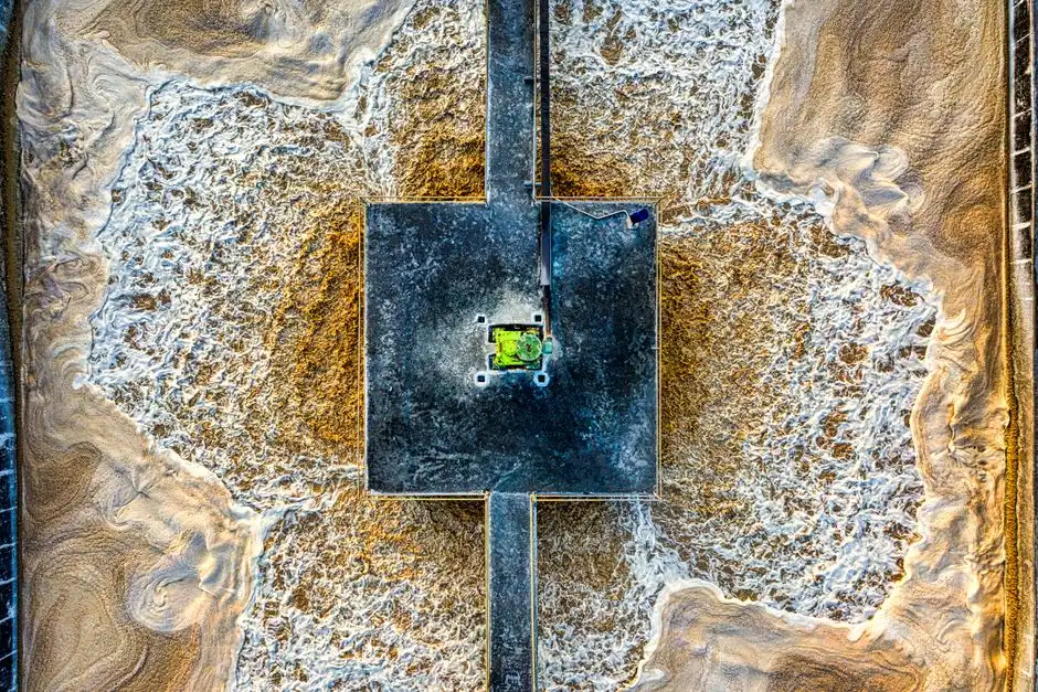
The sizing equation is the same one used for any electrochemical cell: required anode area A = (Q × i_req) / j, where Q is flow in m³/h, i_req is the required coagulant dose equivalent, and j is the design current density. At 10 mA/cm² and 10 m³/h, the active anode area is roughly 11,000 cm² — typically realized as 6–10 parallel plates in a single cell, matching the "six parallel monopolar iron electrodes" configuration documented in the ScienceDirect industrial case (industrial wastewater entry in the S5 table, 20 mA/cm², COD 410 mg/L).
Cell voltage of 5–20 V is typical for a properly designed cell with 2–4 mS/cm conductivity; the total rectifier draw is 1–5 kWh per m³ of treated wastewater, and that figure is dominated by solution resistance and electrode gap rather than by the actual metal dissolution. Two practical design points: keep the electrode gap at 10–20 mm to hold voltage down, and oversize the rectifier by at least 25% so the operator can push current density during a feed-quality excursion without tripping. The cell itself replaces a DAF tank but still needs a downstream lamella or filter press for solids — the EC effluent typically carries 100–300 mg/L TSS that the floating floc does not capture. For plants already evaluating flotation as a downstream step, DAF flotation systems for metalworking are a common follow-on polishing stage. Plate-and-frame filter presses sized from 1 m² (single die line) to 500 m² (multi-line plant) cover the full throughput range and are covered separately in the filter press sizing for wire drawing sludge guide.
EC vs Chemical Coagulation + DAF: Sludge, Energy, OpEx
The incumbent train at most wire drawing plants is polyaluminum chloride or ferric chloride coagulation followed by dissolved air flotation, with a lime or caustic trim for pH. The head-to-head numbers look like this:
| Parameter | Electrocoagulation | Chemical Coagulation + DAF |
|---|---|---|
| Sludge volume | Baseline; 20–30% less solids because no SO₄²⁻ / Cl⁻ counter-ions added (S3, 2023) | Higher; counter-ions add mass |
| Energy | 1–5 kWh/m³ on the rectifier | Negligible electricity on dosing |
| Reagent cost | Electrode wear only (Fe or Al plate consumption) | 200–600 g/m³ PACl or FeCl₃ at $0.30–0.80/kg |
| Operator time | No daily polymer make-down, no pH swing | Daily polymer prep, jar tests, pH trim |
| Footprint | One cell replaces coag + floc + DAF (30–50% smaller) | Three vessels in series |
| Sludge handling | Sent to a filter press for EC sludge dewatering | Sent to a filter press after a lamella clarifier for EC effluent polishing |
The qualitative sludge claim — "high pollutant removal efficiency and generates less sludge when compared with other techniques" — comes from the ScienceDirect EC overview (S3, 2023). The reagent-cost number is the realistic PACl/FeCl₃ dosing range for an oil-in-water emulsion at 2,000–8,000 mg/L COD. The footprint figure of 30–50% is the typical retrofit saving when an EC cell replaces a three-vessel train in an existing building.
Sludge Handling and Downstream Polishing
The floating metal-hydroxide floc, now bound with emulsified soap and metal fines, is scraped from the cell surface and sent to a filter press for dewatering. The filtrate is low in suspended solids but still carries dissolved soap fragments, so it returns to the EC cell inlet for another pass rather than going forward to discharge. Plate-and-frame presses in the 1–500 m² filter area range cover everything from a single-die drawing line to a multi-line plant producing several m³ of wet cake per shift.
Treated water from the EC cell typically still needs pH trim and a polishing filter — multi-media or ultrafiltration — before it can be recycled to the rinse loop or discharged to sewer. The COD reduction at the EC cell is 80–95%, but residual dissolved COD in the 200–500 mg/L range will usually exceed a 40 CFR 433 metal finishing limit. For zero-liquid-discharge lines, the EC effluent is the right feed for an industrial RO unit, which is where a reverse osmosis system for ZLD polishing earns its place. A multi-media filter for EC effluent polishing in front of the RO is standard to keep the membrane from fouling on residual soap. The integrated solids-and-water train is also covered for related cable-mill streams in the cable manufacturing wastewater sludge guide.
Selection Checklist and ROI Framework
Use this rule when the project is on the table with procurement. Select EC when influent COD exceeds 1,500 mg/L, the soap/fatty-acid load dominates the organics, the site is space-constrained, or the discharge permit restricts chloride or sulfate addition. Skip EC when flow is above ~50 m³/h with a low organic load — at that scale and influent strength, chemical DAF is cheaper to build and easier to operate, and the electrode wear cost on a large EC cell starts to bite. The realistic payback window for the right application is 12–24 months when soap and lubricant recovery, avoided sludge-hauling cost, and eliminated polymer purchase are all credited — a typical industry figure, not a guarantee, and it depends heavily on local tipping fees and lubricant value.
Vendor evaluation criteria: cell construction in PP or FRP (no steel in contact with the electrolyte), rectifier sized with at least 25% margin, automatic electrode-feed on iron systems to compensate for plate consumption, and an integrated PLC with current-density trending so the operator can see passivation starting before the cell voltage spikes. A small pH and conductivity trim dosing skid on the inlet and a downstream filter press round out the package. Anything missing on that list is a red flag.
Frequently Asked Questions
What removal efficiency can electrocoagulation achieve for soap and lubricant in wire drawing wastewater?
Peer-reviewed EC studies report 96.7–99.9% removal of organics and suspended solids at current densities from 0.8 to 20 mA/cm² and residence times of 10–120 minutes, depending on electrode pair and influent strength (per the ScienceDirect EC overview, S5). On a wire drawing rinse stream at 5–15 mA/cm² and 30–60 minutes, expect COD reduction of 80–95% in a single pass.
Should I use iron or aluminum anodes for wire drawing rinse water?
Choose iron for pH 5–9 effluent carrying copper or iron fines and tight discharge limits on total aluminum. Choose aluminum when the influent is soap/fatty-acid-dominated with low TDS and neutral pH, where Al reaches ~99% removal at 2.67 mA/cm². Avoid Al in alkaline, high-carbonate rinse water because the passive oxide layer drives cell voltage upward over weeks.
How does EC sludge yield compare with chemical DAF?
EC produces 20–30% less dry solids than chemical coagulation because no sulfate or chloride counter-ion enters the water — the only mass added is the dissolved electrode metal and the sorbed contaminant (per the ScienceDirect EC overview, S3, 2023). On a 10 m³/h wire drawing line this typically means 200–500 kg/day less wet cake to haul, at 1–5 kWh/m³ of rectifier power.
How often do EC electrodes need replacement on a wire drawing line?
At 10 mA/cm² and 50% duty cycle, an iron anode pair typically lasts 12–24 months of continuous operation before plates thin to the replacement setpoint, and aluminum anodes last roughly 60–80% of that interval because of the lower equivalent weight. Plan for annual electrode inspection and a multi-year plate-replacement budget, not a monthly one.