
What an Ultrafiltration System Does in a Sugar Mill
An ultrafiltration system for sugar mill wastewater is a low-pressure hollow-fiber membrane barrier, typically rated at 0.01–0.1 micron pore size with 0.03 micron as the industrial norm, installed to remove suspended solids, colloids, bacteria, high-molecular-weight organics, and emulsified oil and grease from sugar factory effluent streams. UF does not remove monovalent ions, small organics, or sugars in solution, which is why the reuse target dictates whether UF stands alone or sits ahead of reverse osmosis: for boiler feed, hardness-free low-TDS water demands an industrial RO system downstream, while for irrigation or general process reuse, UF alone is often sufficient. The Brazilian Bom Sucesso mill in Goiatuba, Goiás, anchors the regional case: the facility pairs 80 PureULTRA UF II PHF-107-V modules with 96 MICRODYN RO 8040-BW-400 elements to deliver permeate with extremely low TDS, zero hardness, and minimal biofilm risk, all under chemical-free operation with remote monitoring (S3). Brazil alone accounts for 21% of world sugar cane production, making UF + RO a proven regional solution (S3). A standard HydropureWater hollow-fiber UF system is rated for 2,000–40,000 L/h capacity, tolerates up to 300 ppm feed turbidity, and integrates automatic backwash with air scour (HydropureWater Product Catalog P17, 2026).
Sugar Mill Wastewater Characteristics That Drive UF Design
Sugar mill wastewater is a blend of floor and equipment washing, mill-house cleaning, process spills, boiler blowdown, cooling tower blowdown, lab and utility drains, condensate streams, and periodic cleaning operations (S5). The composite stream is high in organic matter, suspended solids, oil and grease, nutrients, dissolved salts, and cleaning chemicals, and it is highly variable: the same plant can swing from dilute cooling-tower bleed to concentrated cleaning effluent within a single shift. Equalization is a primary requirement for a reliable sugar mill ETP because UF must tolerate peak shock loads, not just average conditions (S5). Temperature is the second design driver: condensate and cleaning streams run hot, and PVDF UF membranes tolerate this where PES alternatives begin to deform. Sugar mill influent to UF is also characterized by oil and emulsified grease, which is why a rotary mechanical bar screen for gross solids and a dissolved air flotation (DAF) unit for oil and grease must sit ahead of the membrane rack, or fouling accelerates and CIP frequency doubles. The Brazilian case describes the same challenge in surface water: feed loaded with sediments, dissolved minerals, salts, organic matter, and pollutants (S3), which is why the UF pretreatment decision there maps directly onto sugar mill wastewater service.
Three Positions for UF in a Sugar Mill Treatment Train
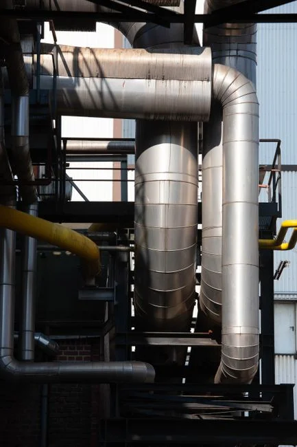
UF can occupy three distinct positions in a sugar mill treatment train, each requiring a specific design approach. Position 1 — UF as raw-water pretreatment to RO for boiler feed or cooling-tower makeup. The Bom Sucesso case used 80 PureULTRA UF II PHF-107-V modules directly ahead of 96 MICRODYN RO 8040-BW-400 elements (S3); the design driver is SDI15 reduction so RO membranes can run at design flux without biofouling. Position 2 — UF as post-biological polishing after aerobic or anaerobic treatment, ahead of discharge or reuse. This is the advanced treatment step described in the practical ETP guide for sugar mills, with turbidity and TSS polishing as the driver (S5). Position 3 — UF as a standalone reuse barrier for irrigation or process water. Lowest CAPEX, but UF does not remove salinity, so reuse is limited to salt-tolerant crops or non-critical rinse water. Anaerobic treatment is not automatically suitable for every sugar mill (S5), so Position 2 trains often pair aerobic biological treatment with UF polishing rather than relying on a secondary clarifier alone.
| Position | Water Quality Target | CAPEX / OPEX Profile | Fouling Risk |
|---|---|---|---|
| 1. UF → RO (boiler feed, cooling makeup) | SDI15 <2, hardness-free, low-TDS permeate | Highest CAPEX (membranes + high-pressure pump); lowest OPEX per m³ of reusable water | Lowest (RO protected, CIP interval 1–4 weeks typical) |
| 2. UF after biological (discharge / reuse polish) | TSS <1 mg/L, turbidity <0.5 NTU | Mid CAPEX; mid OPEX (biological stage dominates OPEX) | Moderate (depends on biological effluent quality) |
| 3. UF standalone (irrigation / process reuse) | TSS <5 mg/L, no pathogen reduction credit unless log-rated | Lowest CAPEX; lowest OPEX | Low to moderate (no downstream RO protection) |
For most sugar mill greenfield or upgrade projects, Position 1 paired with a downstream industrial RO system delivers the strongest reuse economics because boiler feed is a continuous, high-value demand stream.
UF Operating Parameters and Material Selection for Sugar Mill Duty
The defensible UF specification for sugar mill duty follows specific performance standards. Pore size: 0.03 micron is the industrial hollow-fiber norm; smaller pores raise TMP and cleaning frequency without measurable sugar mill benefit, while larger pores leak colloids and defeat the SDI15 reduction goal. Flux band: typical operating range is 40–80 LMH for high-organic sugar mill feed, with conservative design at 50–60 LMH to control fouling on variable-strength streams. TMP: 0.5–1.5 bar clean-water, alarm at ~2.0 bar, chemical clean trigger at ~2.5 bar (vendor-typical values for PVDF hollow-fiber UF on sugar mill feed). Backwash: automatic backwash plus air scour every 20–60 minutes, integrated on the HydropureWater hollow-fiber UF system (Product Catalog P17, 2026). Chemical cleaning: CIP every 1–4 weeks with NaOCl (typically 500–1,000 mg/L free chlorine) plus citric acid is standard for sugar mill duty; the Bom Sucesso case required chemical-free operation, which favors UF as the cleanest pretreatment step before RO (S3). Material — PVDF vs PES: PVDF tolerates higher temperatures (typically up to 40–45°C continuous vs ~35°C for PES), a wider pH cleaning window (1–12 vs 2–10), and stronger oxidant tolerance. PES is cheaper but limits cleaning chemistry and shortens membrane life on hot sugar mill streams, so PVDF is the correct primary selection axis.
| Parameter | PVDF Hollow-Fiber (Sugar Mill Recommended) | PES Hollow-Fiber |
|---|---|---|
| Pore size | 0.03 micron | 0.01–0.05 micron |
| Max continuous temperature | 40–45°C | ~35°C |
| Operating pH range | 1–12 | 2–10 |
| Oxidant tolerance (NaOCl) | Up to ~2,000 mg/L during CIP | Limited, typically ≤500 mg/L |
| Typical flux on sugar mill feed | 50–60 LMH design | 40–50 LMH design |
| Membrane life | 5–8 years | 3–5 years |
Sourcing RO and UF membrane spares from the same vendor as the original train simplifies CIP chemistry matching and module replacement cycles.
Integrating UF with RO for Boiler Feed and Cooling Reuse
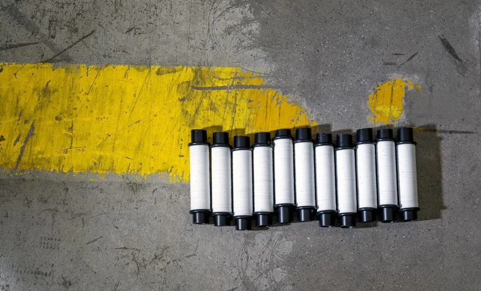
Sugar mill boiler feed water must be hardness-free, low-TDS, and free of biofilm precursors, and RO alone cannot meet this reliably without UF pretreatment (S3). The UF → RO pairing delivers three quantifiable benefits that justify the CAPEX in any RFQ. First, SDI15 reduction: UF cuts the silt density index from >5 (raw surface water or treated wastewater) to <2, which is the design ceiling most RO membrane manufacturers warranty at. Second, RO membrane life extension: with stable, low-SDI feed, RO membrane life extends from a typical 3 years on unprotected feed to 5+ years in sugar mill service. Third, fouling rate drop: RO normalized flux decline slows significantly when particulates, colloidal organics, and microbial precursors are stripped upstream, which directly reduces CIP frequency on the more expensive RO stage. The Brazilian installation's permeate TDS is described as "extremely low" (S3) precisely because UF removes the particulates and microbial precursors that would otherwise foul RO. The system is monitored remotely (S3), which supports the case for automated UF + RO in sugar factories with limited operator headcount, particularly during off-season standby. Where boiler feed hardness must be polished further or condensate is being recycled, an industrial water softener can be staged after RO or used on the make-up stream independently.
Sizing a UF System for a Sugar Mill: Flow, Flux, and Module Count
The sizing walkthrough requires balancing design flow with membrane surface area. A sugar mill targeting 1,000 m³/day of RO-ready water, operating 20 hours per day to leave a 4-hour equalization and backwash window, requires 50 m³/h (833 L/min) of design flow on the UF rack. Applying a conservative design flux of 60 LMH on PVDF hollow-fiber modules with ~20 m² active area per module gives a required membrane area of roughly 833 m², which translates to approximately 42 modules in service (with redundancy typically pushing the installed count to 48–56). This requirement falls comfortably in the mid-range of the 2,000–40,000 L/h capacity band offered by the HydropureWater hollow-fiber UF system (Product Catalog P17, 2026), with skid count decided by plant footprint and redundancy philosophy rather than hydraulic limit. Equalization is a hard prerequisite: without it, peak flows can double the required UF capacity (S5), so the upstream multi-media filter and equalization tank should be sized to damp the 2–4× diurnal swings typical of sugar mill operations. Two practical notes for the RFQ: oversize the backwash pump and air scour blower by 20–30%, because sugar mill organics shorten backwash cycles, and budget for a CIP skid sized to circulate NaOCl and citric acid through the entire rack at the design cross-flow velocity.
Frequently Asked Questions
Hollow fiber or plate-and-frame for sugar mill UF duty?
Hollow fiber dominates sugar mill UF duty because it tolerates higher suspended solids, supports efficient backwash, and air-scours cleanly. Plate-and-frame modules are used in some high-viscosity food applications but are rarely specified for sugar mill ETP service where backwash-driven fouling control is the primary design lever.
Where does UF sit in a sugar mill ETP?
UF has three viable positions: as raw-water or clarified-effluent pretreatment to RO for boiler feed and cooling-tower makeup, as post-biological polishing before discharge or reuse, or as a standalone reuse barrier for irrigation. The reuse target — boiler feed, cooling makeup, discharge, or irrigation — determines which position is correct.
How is UF fouling controlled on sugar mill feed?
Fouling is controlled by automatic backwash plus air scour every 20–60 minutes to remove the surface fouling layer, followed by CIP every 1–4 weeks with NaOCl and citric acid to recover flux. Adequate pretreatment (screening, oil/grease removal via DAF, and equalization) is what keeps the CIP interval in the 1–4 week band rather than the 1–3 day band that a poorly pretreated system would require.