Why Data Center Cooling Tower Blowdown Is a Hard RO Feed
Cooling tower blowdown at a hyperscale data center running 6–8 cycles of concentration is a colloidal concentrate rather than a softened municipal stream. Operators typically measure total dissolved solids (TDS) at 1,500–3,000 mg/L, turbidity at 200–600 NTU, and colloidal silica at 50–200 mg/L, while free oil and grease (FOG) and oxidizing biocide residuals stay low because most hyperscaler loops are DI-fed and tightly chemistry-controlled (HydropureWater field data, 2026). That profile matters because reverse osmosis (RO) membranes fail on the colloidal and organic fraction that slips past softeners and multimedia filters, not on dissolved ions.
Academic fouling autopsies classify RO foulants into four groups: inorganic scale, colloidal or particulate matter, dissolved organic carbon, and biological matter. Combined organic plus colloidal fouling accounts for roughly 70% of diagnosed RO failure causes in feedwater autopsies published between 2011 and 2021 (per the PMC RO/NF fouling review, 2024). The same review notes that even with low-pressure membrane (LPM) pretreatment advances, particulate and colloidal fouling has persisted as a measurable autopsy category through 2021, proving that conventional clarification is insufficient.
Closed-loop reuse programs targeting up to 90% water recovery with 99.9% pollutant removal are achievable when the RO step is protected by the right pretreatment train (per a 2024 ScienceDirect circular water framework). The economic proof point is refinery-scale: Chevron El Segundo has run recycled cooling-tower water since 1995 and reports a $2.3m reduction in cooling-water costs and a 15% reduction in cooling-tower chemical costs after the RO reuse retrofit (per the JWENT RO refinery study). Translating those economics to a hyperscaler campus, the pretreatment decision in front of an industrial RO system determines the operating cost.
How UF and DAF Actually Treat Colloidal Solids
Ultrafiltration (UF) and dissolved air flotation (DAF) utilize distinct physical mechanisms to treat colloids, dictating which stream they can protect.
UF acts as a size-exclusion barrier. A hollow-fiber poly(vinylidene fluoride) (PVDF) membrane rated at 0.03 μm absolute rejects suspended solids, sub-100 μm colloids, bacteria, and most high-molecular-weight organics. A typical skid-mounted hollow-fiber UF system sized at 2,000–40,000 L/h with automatic backwash and air scour holds effluent turbidity below 1 NTU continuously and drives the silt density index at 15 minutes (SDI15) below the 3 threshold required for stable flux in brackish RO membranes. UF removes turbidity, total suspended solids (TSS), and chemical oxygen demand (COD) by particle class: roughly 98% turbidity and TSS removal, with 30% COD removal on refinery cooling-tower pilot work (per the JWENT RO refinery study).
DAF relies on buoyancy separation. Micro-bubbles (typically 30–70 μm) attach to oil droplets, grease, and floatable suspended solids, lifting them to the surface as a float layer for skimmer removal. A DAF system sized at 4–300 m³/h is effective for free oil, grease, and low-density flocs but does not reject dissolved species; its bubble-particle contact efficiency collapses below roughly 100 μm, the exact colloidal size range that drives RO fouling. DAF effluent turbidity on cooling-tower blowdown typically lands at 30–80 NTU and SDI15 at 4–8, exceeding the design feed threshold for stable RO operation.
Autopsy data confirms that colloidal and particulate fouling remains a primary cause of RO failure (per the PMC RO/NF fouling review, 2024). UF provides the mechanism to keep those particles out of the RO feed; DAF does not.
UF vs DAF on a Data Center Blowdown Stream: Head-to-Head Parameters
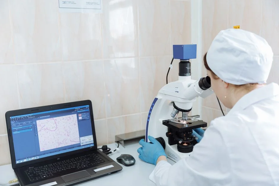
The numbers below reflect typical operating values for 6–8 cycle-of-concentration cooling-tower blowdown pretreated for brackish RO. UF delivers near-RO-ready effluent; DAF delivers clarified-but-colloidal effluent that requires a polishing membrane.
| Parameter | DAF (dissolved air flotation) | UF (ultrafiltration, 0.03 μm) |
|---|---|---|
| Feed turbidity | 200–600 NTU | 200–600 NTU (often after MMF) |
| Effluent turbidity | 30–80 NTU | <1 NTU |
| TSS removal | 60–85% | ~98% (per JWENT RO refinery study) |
| SDI15 effluent | 4–8 (above RO design) | <3 (meets RO design) |
| Footprint per 100 m³/h | ~15–25 m² incl. sludge holding | ~3–5 m² for skid-mounted cassettes |
| Coagulant / polymer demand | Cationic flocculant (often polyDADMAC) required; residual carries over | Coagulant typically removed or re-engineered |
| Waste-solids handling | Float layer + coagulant-laden sludge | Backwash solids, low volume |
| RO CIP frequency | 6–10×/year | 1–2×/year |
| Expected 5-yr OPEX band | Lower chemical cost, higher RO CIP and lost flux | Higher polymer/membrane cost, much lower RO CIP |
DAF systems routinely dose cationic flocculants—frequently polyDADMAC—to grow settleable and floatable flocs, causing residual polymer to carry into the RO feed. Low levels of polyDADMAC residual have been shown to degrade downstream cooling-water treatment performance, complicating RO clean-in-place (CIP) recovery and compromising cooling-water chemistry (per the PMC RO/NF fouling review, 2024). UF allows coagulation to be dropped or re-engineered, ensuring the RO feed sees water rather than polymer.
The footprint difference is also significant. DAF consists of a wide tank with a sludge hopper, while UF utilizes a vertical cassette skid. At 100 m³/h of blowdown, the 15–25 m² DAF footprint versus the 3–5 m² UF footprint is the difference between a dedicated clarifier room and a skid in the corner of the RO hall—a vital constraint on a hyperscaler campus. The accompanying RO/UF membrane elements inherit that footprint advantage and run longer between CIPs due to the cleaner feed.
When DAF Still Wins: Hybrid and Retrofit Scenarios
DAF is not the optimal choice for a greenfield, sealed DI-fed hyperscaler loop, but it is effective on streams where FOG, free oil, or corrosion debris dominates the foulant mix.
If the cooling-tower basin is open, the loop carries corrosion-inhibitor residues, or coil leaks introduce free oil, a DAF system as primary clarification protects the downstream membrane from irreversible oil blinding. Refinery pilots confirm that a DAF + UF + RO train is the most resilient configuration for oily cooling-tower blowdown, with the DAF unit stripping free oil and floatable solids before the UF polishes sub-100 μm colloids (per the JWENT RO refinery study). For data-center retrofits on older open basins with aluminum or iron hydroxide floc carryover, this hybrid train is the preferred solution.
For a greenfield data center with a sealed, low-FOG, DI-fed loop, the simpler and more cost-effective train is a multi-media filter for roughing, followed by UF, then RO—eliminating the DAF tank entirely. An automatic chemical dosing system on the RO antiscalant line is the only chemistry required in this scope.
Decision Framework for the Campus Utilities Engineer
The following questions help determine the optimal configuration for your campus profile.
| Question | If yes | If no |
|---|---|---|
| 1. Is the loop sealed DI-fed or open with corrosion inhibitors? | Skip DAF; go MMF → UF → RO | Keep DAF for debris and inhibitor residue |
| 2. What SDI15 does the RO design require? | ≤3: UF mandatory / 3–5: UF preferred / >5: DAF optional | Re-rate the RO feed spec or upgrade pretreatment |
| 3. Is the campus reuse mandate ≥90%? | UF required to hit reuse targets reliably (per ScienceDirect circular water framework, 2024) | DAF tolerable if reuse target is <70% |
| 4. Capex vs OPEX priority? | DAF capex ~40–60% lower; UF OPEX payback in 18–30 months via lower RO CIP and higher flux | Default to UF; revisit if capex is hard-capped |
For the 2026 data-center campus standard—sealed DI-fed loop, reuse mandate ≥90%, RO design feed SDI15 ≤3—the default solution is UF in front of the industrial RO system, with DAF retained only as an edge-case polishing or retrofit technology on open or oily loops. Cross-checks against a pharma-grade UF vs DAF comparison and the broader membrane fouling engineering guide confirm that a 0.03 μm absolute barrier is superior for colloidal control. For campus OPEX modeling, pair this decision with the RO vs ion exchange verdict for blowdown reuse.
Frequently Asked Questions
What SDI15 does an RO membrane actually need?
Stable brackish RO operation requires SDI15 ≤3 at the RO feed; spiral-wound elements tolerate 3–5 with flux derating, and SDI15 above 5 is widely treated as a CIP-accelerating feed spec. UF routinely delivers SDI15 below 3 on cooling-tower blowdown, while DAF effluent sits at 4–8 (per HydropureWater field data, 2026).
How often will the RO need CIP if I run on DAF-only pretreatment?
On 6–8 cycle cooling-tower blowdown, DAF-only pretreatment drives RO clean-in-place (CIP) frequency to 6–10 cycles per year because the sub-100 μm colloid fraction passes through DAF and deposits on the RO surface (HydropureWater field data, 2026). Adding UF ahead of RO drops CIP frequency to 1–2 cycles per year.
Is polyDADMAC a real compatibility problem for the cooling-water program downstream?
Yes. DAF regularly doses cationic polyDADMAC to grow floatable flocs, and residual polymer carryover has been shown to degrade downstream cooling-water treatment program performance and complicate RO CIP chemistry (per the PMC RO/NF fouling review, 2024). UF lets the operator drop or re-engineer that coagulant dose.
When does a DAF + UF hybrid train make sense for a data center?
Hybrid DAF + UF + RO is the right train on open cooling-tower basins with FOG carryover, free oil from coil leaks, or heavy iron and aluminum hydroxide floc from corroding carbon-steel piping (per the JWENT RO refinery study). Sealed DI-fed hyperscaler loops do not require the DAF stage.
What reuse rate can a data center hit with UF + RO on blowdown?
Closed