The Grand Bay Mining/Metals Wastewater Problem in 2026
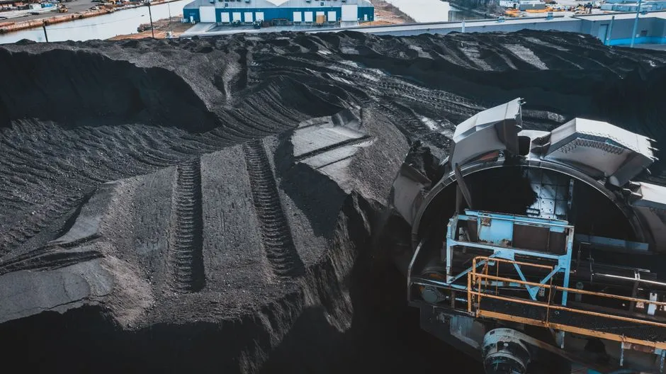
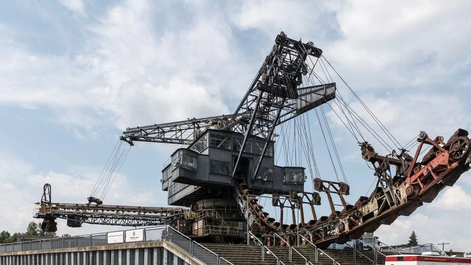
Grand Bay-area mining, mineral processing, and metals fabrication plants in 2026 produce a wastewater envelope that no single technology was designed to handle cleanly. Crushing and milling circuits generate high total suspended solids (TSS) that swing from 2,000 mg/L on a normal shift to over 8,000 mg/L after a mill reline. Flotation circuits leave residual xanthate, dithiophosphate, and frother residues in the 20–150 mg/L range. Metals fabrication lines (cutting fluids, drawing compounds, hydraulic leaks) contribute an intermittent oil/grease sheen that is rarely above 100 mg/L but trips a discharge violation on contact. Influent flow into the treatment house routinely swings 2.5:1 between day and swing shift. Federal effluent limits under 40 CFR Part 440 (Ore Mining and Dressing Point Source Category) govern direct discharges from active ore mines and from mills that process ore, with TSS, settleable solids, and metal limits set per subcategory (e.g., Subpart B for base/precious metals, Subpart C for ferrous ores). Plants discharging to a local POTW sit under separate, often tighter, sewer-use ordinances.
For those envelopes, a single clarifier or a single DAF unit rarely wins on its own. Field data published in 2026 by Ecologix shows the two technologies landing on opposite sides of the same problem: a food plant hit 95% oil and grease removal with a DAF, while a mining facility with heavy sediment loads cut solids by 90% with a clarifier at lower cost (Ecologix 2026 selection guide). The choice is wastewater-specific, not industry-default — which is why a framework beats a rule of thumb.
DAF vs Clarifier: How Each Technology Actually Works
A dissolved air flotation system separates contaminants by buoyancy rather than gravity. A sidestream of clarified effluent is pressurized to ≥5 bar in a saturation vessel, where compressed air dissolves into the recycle water; when the pressurized recycle is released back into the main flotation tank through a pressure-relief nozzle, the dissolved air comes out of solution as a cloud of 10–100 µm microbubbles (wastewatermachinery 2026 mining DAF spec). Those bubbles nucleate on coagulated flocs, on oil droplets, and on fine particles whose density is close to water, lifting them to the surface in a 3–5 minute residence time where a rotating skimmer scrapes them off as float. The float solids cake is typically 3–6% dry solids — thick enough to feed a filter press without a thickener.
A gravity clarifier — and specifically the inclined-plate lamella clarifier — relies on the opposite force. Suspended solids settle under gravity through a stack of parallel plates inclined at 55–60°, which shortens the effective settling distance and raises the surface loading rate to 20–40 m/h versus 1–2 m/h for a conventional circular clarifier (per lamella clarifier design references). Underflow is scraped or pumped from the bottom cone at 1–3% dry solids, which usually needs a thickener or a filter press before disposal. There is no air system, no saturation vessel, no skimmer drive — the mechanical inventory is a sludge pump and a rake mechanism.
The mechanical difference dictates the application split. DAF wins on low-density particles, emulsified oils and FOG, and fines below roughly 50 µm; clarifiers win on heavy, readily settleable mineral solids, especially coarse silica, iron oxide, and mill scale. Both can be circular or rectangular, but rectangular lamella designs typically deliver higher solids throughput per m² of footprint for mining flows because they accept variable flow better along the long axis.
Side-by-Side Parameter Comparison
Use the table below to map your plant's influent data against the technology envelopes. Numbers reflect vendor-published 2026 data and published case studies, not aspirational marketing claims.
| Parameter | DAF system | Gravity / Lamella clarifier |
|---|---|---|
| TSS removal | Up to 97% (wastewatermachinery 2026) | ~90% in mining case study (Ecologix 2026); 70–85% typical on fines |
| COD removal | 60–80% (wastewatermachinery 2026) | Lower unless paired with coagulant dosing; typically 30–50% |
| Oil & grease / FOG | ~95% in food case study (Ecologix 2026); handles emulsified oils | Weak on emulsified FOG; ~70% on free oil only |
| Particle size window | Best on fines <50 µm and low-density flocs | Best on settleable solids >50–100 µm |
| Hydraulic capacity per unit | 3–120 m³/h per single module (wastewatermachinery DAF-003 to DAF-120) | Modular lamella packs; capacity scales with plate area, not a single model line |
| Footprint per m³/h | Compact skid; ~3–5× smaller than a conventional circular clarifier of equal flow | Lamella design narrows the gap vs DAF, but concrete tank footprint is still larger |
| Dry weight (DAF skid) | 1,500–10,000 kg across DAF-003 to DAF-120 (wastewatermachinery 2026) | Civil-works dominant; mechanical equipment weight is secondary |
| Flow swing tolerance | High; 3–5 min residence buffers 2:1 swings | Lower; rapid swings resuspend settled blanket |
| Chemical demand | Coagulant + flocculant; A/S ratio optimization recommended (wastewatermachinery 2026) | Coagulant; flocculant optional but improves capture on fines |
| O&M complexity | Air compressor, saturation vessel, skimmer drive, nozzle maintenance | Sludge pump, rake mechanism, plate cleaning |
| Float/underflow solids | 3–6% dry solids float, ready for filter press | 1–3% underflow, usually needs thickening |
For plants sizing against a target hydraulic load, the HydropureWater dissolved air flotation (DAF) system covers the 3–120 m³/h range in a single skid, and the HydropureWater high-efficiency lamella clarifier covers equivalent flows in a rectangular inclined-plate footprint.
5-Question Decision Framework for Grand Bay Plants
Score each question Yes (1) or No (0) against your own jar test and 24-hour composite sampling. Tally the points at the end.
- Is your TSS dominated by settleable coarse particles, or by fines <50 µm? Coarse settleable solids → clarifier-leaning. Fines and colloidal material → DAF-leaning.
- Is oil/grease or flotation reagent residue measurable at >50 mg/L? Yes → DAF first. Xanthate and dithiophosphate residues ride bubbles effectively; they slip through a clarifier.
- Does influent flow swing more than 2:1 across a shift? Yes → DAF tolerates it better thanks to the 3–5 minute residence time. Clarifier blankets tear under that swing.
- Is your available footprint under 50 m² for the primary clarifier? Yes → DAF. A rectangular lamella clarifier handling 50 m³/h typically wants 60–90 m² of plan area including sludge sump and launder.
- Are you targeting direct discharge under 40 CFR Part 440 with heavy metals in the stream? Yes → either primary still needs pH adjustment and metal precipitation upstream or downstream. DAF removes metal-bearing suspended solids efficiently, but dissolved metals (Cu, Pb, Zn, Ni) require hydroxide or sulfide precipitation regardless of which clarifier you lead with.
Scoring: 0–1 DAF-leaning answers → clarifier primary, with DAF as polish if oil/grease appears. 3+ DAF-leaning answers → DAF primary, with lamella as backup for shock loads. Mixed answers with both particle-size and oil concerns → hybrid flowsheet. This is the same scoring logic used in our DAF vs clarifier selection guide for fabricated metals plants and our companion DAF vs clarifier selection for chemicals plants — the technology envelope is similar enough that the same five questions hold.
CAPEX, Footprint, and Operating Cost Snapshot
Procurement managers typically ask three numbers: equipment CAPEX per m³/h, civil and installation cost as a multiple of equipment, and OPEX per m³ treated. Use the following bands to anchor a budget conversation in 2026 dollars; the bands are intentionally wide because site conditions drive the final 30%.
| Cost dimension | DAF primary | Lamella clarifier primary |
|---|---|---|
| Equipment CAPEX band per m³/h | Higher per m³/h for the skid itself; offset by minimal civil work and shop assembly | Lower per m³/h for plate-pack hardware, but concrete tank and launder civil works add 40–80% to installed cost |
| Footprint per m³/h | 3–5× more compact per m³/h than a conventional clarifier (wastewatermachinery 2026) | Larger plan area; rectangular lamella narrows but does not close the gap |
| Main energy draw | Recycle pump + air compressor (typically 0.5–1.5 kWh per m³ treated) | Sludge pump + rake drive (typically 0.1–0.3 kWh per m³ treated) |
| Chemical OPEX | Coagulant + flocculant; A/S ratio tuning drives 10–20% polymer savings (wastewatermachinery 2026) | Coagulant; flocculant optional |
| Sludge handling downstream | Float at 3–6% DS — feeds a plate and frame filter press directly | Underflow at 1–3% DS — usually needs a thickener or larger press |
| Automation & controls | PLC panel with VFD on recycle pump recommended (wastewatermachinery 2026) | Simpler controls; rake torque and sludge pump VFD only |
For both flowsheets, an automatic chemical dosing system tied to a flow-paced signal cuts polymer consumption 10–20% and stabilises effluent quality during shift changes. If your site already produces a mixed influent that swings in pH, a multi-media filter cost and sizing guide will help you plan the polishing stage that typically follows the primary clarifier.
Recommended Flowsheets for Grand Bay Mining/Metals Plants
Three equipment trains cover the bulk of Grand Bay mining and metals-fab influents. Copy the train that matches your Q1–Q5 score into a P&ID; sizing modules against peak shift flow, not average flow.
- Flowsheet A — DAF primary. Equalization basin → coagulant/flocculant dosing → DAF unit → clarified water to pH adjustment / metal precipitation → multi-media filter → discharge. Float to filter press. Best for streams with oils, flotation reagents, and fines below 50 µm.
- Flowsheet B — Lamella clarifier primary. Equalization basin → coagulant dosing → high-efficiency lamella clarifier → clarified water to secondary treatment → discharge. Underflow to thickener or directly to filter press. Best for coarse heavy-sediment tailings water with low oil content.
- Flowsheet C — Hybrid (recommended for variable influent). Equalization → DAF as fines/oil polish → lamella clarifier as bulk settler, OR lamella first then DAF as a polish step. Addresses both the coarse-solids envelope and the fines/oil envelope in one train, with each unit handling a smaller fraction of the total load. The HydropureWater JY integrated water purification skid packages several of these steps into a single shop-assembled unit for tight sites.
Pre-treatment always starts with a rotary mechanical bar screen to protect both DAF nozzles and lamella plate packs from rags, wood, and tramp metal. Peak shift flow typically drives module count: a single DAF-060 handles 60 m³/h, so a 180 m³/h peak needs three units in parallel or a single larger frame.
Frequently Asked Questions
Is DAF or a clarifier better for high-TSS mining wastewater?
It depends on particle size and oil content. For settleable heavy sediment dominated by coarse silica or mill scale, a lamella clarifier is more cost-effective. For streams with fines below 50 µm, residual flotation reagents, or oil/grease, DAF wins on removal efficiency and footprint. Most Grand Bay plants score mixed on the five-question framework and end up on a hybrid flowsheet.
Can a DAF system remove heavy metals?
DAF removes metal-bearing suspended solids very effectively, which is why it is widely used in mining and mineral processing. Dissolved metals (Cu, Pb, Zn, Ni, Cd) require pH adjustment and hydroxide or sulfide precipitation either upstream of DAF to co-precipitate the metals onto flocs, or downstream of DAF as a dedicated precipitation stage before discharge.
How much floor space does a DAF system need vs a clarifier?
A DAF skid is roughly 3–5× more compact per m³/h than a conventional circular clarifier of the same hydraulic capacity. A rectangular lamella clarifier narrows that gap but still needs more plan area than a DAF for the same flow, plus a sludge sump and launder. For sites under 50 m² of available footprint, DAF is usually the only option without going to a multi-storey clarifier.
What flow rate can a standard DAF unit handle?
Standard packaged DAF units cover 3 m³/h (DAF-003) up to 120 m³/h (DAF-120) per single module, with dry weights from 1,500 kg to 10,000 kg (wastewatermachinery 2026). Plants with peak shift flows above 120 m³/h run multiple units in parallel or specify a custom rectangular basin.
Do Grand Bay mines need pretreatment before either system?
Yes. Install a rotary mechanical bar screen upstream of either a DAF or a lamella clarifier. Bar screening at 3–6 mm openings protects DAF nozzles and lamella plate packs from rags, wood chips, and tramp metal that would otherwise clog the system and force an unscheduled shutdown.