
Why Semiconductor Wastewater in Logan Is Not 'Just Industrial Wastewater'
Semiconductor fab wastewater in the Logan, Utah region behaves differently than the metal-finishing or food-processing streams that most generic clarifier sizing guides assume. The Cache County industrial base around Utah State University and the surrounding research-fab and back-end packaging tenants produces waste streams dominated by chemical-mechanical planarization (CMP) slurry, hydrofluoric acid rinsate, isopropyl alcohol (IPA) rinses, surfactant-bearing post-etch residues, and dilute solvent cleaning baths. CMP slurry particles — typically colloidal SiO2, CeO2, or Al2O3 in the 30–200 nm range — have an effective density of only 1.01–1.05 g/cm3, which means Stokes' law predicts settling times measured in hours, not minutes. Fluoride, HF-derived, and most dissolved metals remain soluble until a dedicated precipitation step; a clarifier or DAF alone will not remove them to Utah DWQ UPDES permit thresholds or Logan City Industrial Pretreatment Program discharge limits. IPA and surfactant-laden rinsate carry a low-density organic layer that refuses to sink. TSS removal targets must be set against colloidal loads that defeat gravity, FOG/surfactant limits cannot be met without flotation, and any reusable water stream must hit upstream of a polishing membrane (RO/UF) for UPW make-up. A conventional lamella clarifier will pass more than half of those particles through under fab upset conditions — and that is why the 2026 selection conversation starts with DAF, not with a settling tank.
DAF vs Gravity Clarifier: How Each Technology Actually Separates Solids
A dissolved air flotation unit separates particles by attaching them to microbubbles that rise to the surface, inverting the direction of separation relative to a gravity clarifier. A recycle stream is pressurized at 4–6 bar in a saturator, dissolving 70–100 mg/L of air; when released through a nozzle into the flotation cell at atmospheric pressure, the air comes out of solution as a cloud of 10–100 µm bubbles, with industrial DAF systems typically delivering 20–50 µm (per SigmaDAF/DAF Corp Micro Bubbler specifications, 2026). These bubbles attach to flocculated particles and lift them at 5–15 m/h rise velocity, where a skimmer removes the buoyant blanket. A gravity or lamella clarifier relies on Stokes' settling, with inclined plates at 55–60° multiplying effective area and pushing surface loading to 20–40 m/h, but only for particles dense enough to overcome hydraulic drag and Brownian motion. The decision pivots on the difference between effective particle density and water density. CMP slurry at 1.01–1.05 g/cm3 will not settle in any practical clarifier residence time, but once flocculated and attached to a 20–50 µm bubble, the aggregate density drops below 0.5 g/cm3 and rises in seconds. DAF sludge typically lands at 2–6% solids float versus 0.5–2% for a settling clarifier (per clean technology review, 2026-08), which directly cuts downstream dewatering cost for any HydropureWater DAF system or HydropureWater lamella clarifier downstream of a fab reactor.
Side-by-Side Performance: DAF vs Lamella Clarifier on Semiconductor Effluent
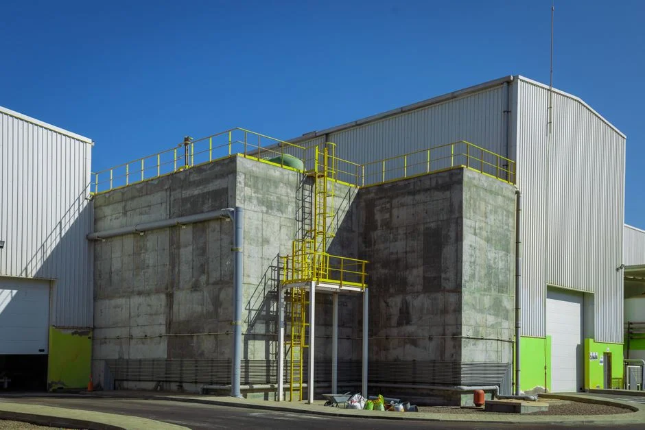
The table below presents typical operating performance for a 50 m³/h fab pretreatment skid (per HydropureWater catalog and S1/S5 field data, 2026). The two technologies diverge most sharply on colloidal and low-density loads, footprint, and sludge dryness.
| Parameter | DAF (HydropureWater / FC-type) | Lamella Clarifier |
|---|---|---|
| TSS removal efficiency | 92–98% (circular FC-type) / 85–90% (rectangular) per DAF Corp 2026 catalog | 60–80% on light colloidal loads; >90% only on dense, well-settling streams |
| FOG / surfactant removal | >95% FOG removal (per cleantechnologypost 2026-08 review) | Poor without prior DAF; depends on skimmer geometry |
| Footprint per 100 m³/h | ~12–20 m² (DAF skid) | ~30–50 m² at 20–40 m/h surface loading |
| Hydraulic loading | 5–30 m³/m²·h baseline; up to 40 with lamella packs; up to 50 in HR-DAF | 20–40 m/h on plates; lower for colloidal loads |
| Sludge dryness | 2–6% solids float (per S5) | 0.5–2% underflow |
| CAPEX class | Medium (skid DAF) to high (HR-DAF with plates) | Low to medium (concrete or coated-steel basin) |
| OPEX driver | Recycle-pump and saturator energy, plus coagulant/polymer | Polymer dose; periodic plate cleaning |
| Best-fit fab stream | CMP slurry, HF rinsate after neutralization, IPA, surfactant-bearing rinsate, RO pretreatment | Low-TSS rinse water (<200 mg/L), no FOG/IPA, large floor available |
For most Logan fab pretreatment duties — CMP slurry, post-etch neutralized streams, IPA and surfactant rinses — the DAF column wins on every row except CAPEX class. Lamella clarifiers have a real edge only on light, non-floating loads where the operator is willing to trade removal efficiency for a tighter capital budget and lower chemical dose.
2026 Decision Framework: Which One Should Your Logan Fab Choose?
Use the four rules below to map your influent data to a specific clarifier topology to ensure compliance with Utah DWQ UPDES / Logan City Industrial Pretreatment discharge expectations under upset conditions.
| Rule | If Your Stream Looks Like This… | Then Choose… |
|---|---|---|
| 1 | Influent TSS > 200 mg/L OR any FOG / IPA / surfactant present | DAF — lamella will underperform and carry floating scum downstream |
| 2 | TSS < 200 mg/L, no FOG, tight CAPEX, large available floor | Lamella clarifier — saves on chemical conditioning and capital |
| 3 | Closed-loop reclaim, UPW make-up, or RO pretreatment | DAF upstream of RO to protect membranes (per S5, DAF-before-UF extends cleaning intervals) |
| 4 | Variable CMP slurry plus acid neutralization steps | Hybrid skid — DAF handles light slurry, lamella polish catches carryover |
For any fab with IPA vapor scrubber condensate, post-CMP cleaning rinses, or any surfactant-bearing stream, Rule 1 forces the choice to DAF. Rule 3 is the reason fabs targeting water reuse do not consider a standalone lamella: a lamella effluent routinely exceeds an SDI of 5, which fouls RO membranes in days. Pairing a HydropureWater DAF system with a HydropureWater industrial RO system is the configuration most often specified for back-end packaging and MEMS lines in the Logan region. For a deeper look at how a fab-skid might also handle metal-bearing rinsate, see the solar cell electroplating wastewater treatment guide, which covers parallel metal-removal skids that often share DAF pretreatment with semiconductor lines.
Footprint, CAPEX and OPEX: What to Budget in 2026
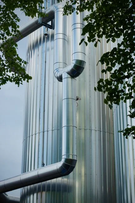
Footprint is the single most under-appreciated constraint in fab support rooms. A packaged 50 m³/h DAF skid typically occupies 6–10 m² of floor area; a lamella clarifier built for the same flow needs 15–25 m² even with inclined plates at 55–60° — a 2–3× multiplier that often determines whether the unit fits inside an existing tool-room chase or forces a costly building extension. CAPEX for a 2026 Logan-area fab pretreatment skid falls into three bands: low (custom-built lamella clarifier in a concrete or coated-steel basin, no integrated chemical conditioning); medium (packaged skid DAF with internal saturator, recycle pumps, and skimmer — typical DAF scope); and high (hybrid DAF + lamella polish + chemical conditioning skid + control panel). OPEX is the part that surprises procurement: DAF operating cost is dominated by the recycle pump and saturator compressor, while lamella clarifier OPEX is dominated by polymer dose and periodic plate cleaning. For fabs with high IPA or surfactant load, DAF wins on chemical OPEX because the bubble-floc attachment step needs only a modest coagulant/polymer dose (typical A/S ratio 0.005–0.06 mL air per mg solids, per cleantechnologypost 2026-08). For clean rinse water, lamella wins. Plan on a HydropureWater automatic chemical dosing system upstream of either clarifier, and on a HydropureWater plate-and-frame filter press downstream to dewater the float or underflow sludge before disposal.
Recommended Configuration for Logan Semiconductor Plants in 2026
Default specification for a 2026 Logan fab pretreatment skid: a HydropureWater DAF system (4–300 m³/h capacity, 13 standard models) with an optional lamella pack for high-rate mode, paired with a HydropureWater automatic chemical dosing system for pH adjustment and polymer flocculation upstream. For UPDES-bound flows, the dosing skid must include a fluoride precipitation stage (typically CaCl2 or lime) ahead of the DAF, since DAF does not remove dissolved fluoride. For fabs targeting water reuse, the train extends to a HydropureWater multi-media filter and a HydropureWater industrial RO system downstream of the DAF; the DAF protects the RO membranes from CMP carryover and, per the S5 hybrid finding, extends UF cleaning intervals. For very small fabs (below 20 m³/h) the COMPACT-class packaged DAF described in S3 — single-skid design at flows up to 66 GPM with integrated chemical conditioning, PLC control, and turnkey installation — is the right fit. For an outside look at how a similar semiconductor pretreatment train is documented in another jurisdiction, see the semiconductor process wastewater compliance guide, and for an analogous heavy-industry comparison to validate the DAF-vs-clarifier logic on a different waste matrix, the DAF vs clarifier mining wastewater guide applies the same framework to a colloidal, high-TSS load.
Frequently Asked Questions
Can a lamella clarifier treat CMP slurry?
A lamella clarifier fails on CMP slurry above roughly 200 mg/L TSS because colloidal 30–200 nm SiO2 or CeO2 particles settle too slowly under Stokes' law; pilot data on colloidal fab streams typically shows only 60–80% TSS removal
Frequently Asked Questions
Should a semiconductor fab use a DAF or a clarifier in 2026?
The selection depends on the influent solids density and required footprint. In 2026, DAF systems are preferred for light, hydrophobic particles or oil-laden streams, typically achieving 90-95% removal of suspended solids with shorter retention times. Clarifiers remain the standard for high-density, inorganic heavy metal precipitates where sludge thickening and long-term mechanical reliability are prioritized over space efficiency.
Can a lamella clarifier remove CMP slurry particles?
Yes, lamella clarifiers are effective for CMP slurry removal, provided the influent is properly conditioned with coagulants and flocculants to increase particle size. Because CMP waste contains sub-micron silica particles, the clarifier must be paired with high-performance polymer dosing to achieve the necessary settling velocities, typically maintaining a surface overflow rate between 0.2 and 0.5 meters per hour to prevent carryover.
What DAF bubble size works best for semiconductor wastewater?
For optimal flotation of semiconductor waste, micro-bubbles ranging from 10 to 50 microns in diameter are required. This size range maximizes the surface area for particle attachment; bubbles larger than 100 microns often lack the buoyancy control required to lift fine chemical-mechanical planarization particles without causing turbulence that disrupts the sludge blanket.
How much floor space does a DAF system save compared to a clarifier?
DAF systems typically occupy 50% to 75% less footprint than conventional circular clarifiers of equivalent capacity. Because DAF units utilize high-rate air flotation to achieve separation in minutes rather than hours, they eliminate the need for large-diameter settling tanks, allowing for high-throughput treatment in compact, modular configurations suitable for constrained fab utility areas.
Is DAF effluent safe to send to reverse osmosis for UPW reuse?
DAF effluent generally requires secondary treatment before entering a reverse osmosis system for Ultra-Pure Water (UPW) reclamation. While DAF effectively removes the bulk of suspended solids and oil, it often leaves residual micro-flocs and dissolved organic carbon that can cause rapid fouling of RO membranes; therefore, media filtration or ultrafiltration is mandatory as a final polishing step to meet standard SDI (Silt Density Index) requirements of less than 3.0.