What Meridian Fabricated Metals Wastewater Actually Looks Like
A typical Meridian stamping and machining shop runs three streams that do not behave the same way in a treatment tank. On top sits free and emulsified tramp oil from stamping presses and CNC sumps — usually 200-1,500 mg/L oil & grease when coolant breaks. In the middle sits a stable emulsion of cutting fluid, often 1-5% semi-synthetic with surfactants that resist gravity separation. On the bottom sits grinding swarf and metal fines (iron, zinc, nickel, occasional chromium) at 200-800 mg/L TSS, plus alkaline or phosphate rinse water at pH 9-12. Flow swings are sharp: a single press dump or a coolant change can triple the load in 15 minutes. This matters for equipment selection because oils float, fines sink, and emulsions stay suspended — and local Meridian POTW pretreatment limits typically constrain oil & grease, TSS, and individual metals (zinc, nickel, lead, chromium) more aggressively than BOD. A single technology tuned to one fraction will miss the other two, so the DAF-or-clarifier question is a matching exercise rather than a binary choice.
DAF vs Clarifier: How the Two Technologies Actually Work
A dissolved air flotation system saturates air into a pressurized recycle stream (typically 60-80 psig) and releases it through needle valves into the flotation cell, producing a cloud of 30-50 micron microbubbles (per S3, Clearwater Industries). Those bubbles attach to chemically conditioned floc and lift oil, grease, and low-density solids to the surface, where a paddle skimmer scrapes them off. Heavier settleable solids drop into a bottom collection zone and are removed by an auger (per S3). A clarifier relies on quiescent gravity settling, with hydraulic residence times of 2-4 hours, so denser particles fall to a sludge hopper. A lamella clarifier inserts 55-60° inclined plates into the tank to shorten the effective settling path and push surface loading to 20-40 m/h, which is roughly 5-10× the rate of a conventional clarifier. Footprint is the trade — a DAF is compact and high-rate, while a clarifier is mechanically simpler (no compressor, no saturator, no recycle pump) but needs more tank volume for the same flow. Both are sensitive to chemistry: a clarifier will function with poor coagulation and still drop coarse solids, while a DAF with the wrong coagulant is an expensive tank (per S5, Spectrum Water) because microbubbles will not attach to unconditioned emulsified oil. Jar-test the chemistry before either unit is specified.
Head-to-Head: DAF and Clarifier on the Parameters That Matter
The table below is built for a CAPEX memo, with numbers derived from comparative data in S1 and equipment specifications in S3 and S5; costs are directional.
| Parameter | DAF | Clarifier (e.g., lamella / FPBC) |
|---|---|---|
| Oil & grease removal | ~95% on conditioned emulsified streams (S1) | ~70% on the same stream (S1) |
| Settleable solids removal | 70-85% (floated + bottom auger fraction, S3) | ~90% on heavy sediment loads (S1) |
| Footprint | Compact; high-rate | Larger tank volume; lamella cuts it ~5-10× |
| CAPEX (directional) | Higher (compressor, saturator, recycle pump, controls) | Lower (tank, plates, sludge scraper) |
| OPEX (directional) | Higher energy + polymer consumption | Lower energy, modest polymer |
| Energy use | Moderate — air compressor and recycle pump dominate | Low — sludge rake drive only |
| Operator skill | Higher — chemistry, saturator pressure, air-to-solids ratio | Lower — sludge wasting and plate inspection |
| Flow sensitivity | Tolerates oily shock loads well (S5) | Tolerates sustained high TSS well |
| Standard materials | 304SS; 316SS or polypropylene for corrosive rinses (S3) | 304SS / FRP / coated carbon options |
| Typical flow range | 4-300 m³/h packaged; 50-1,000 gpm Spectrum packaged (S5) | Larger tanks; lamella modules scale linearly |
DAF carries a higher upfront and operational cost because of the air compressor, saturator, and recycle pumps (per S1), whereas a clarifier is cheaper to build and run but needs more tank volume for equivalent flow. Modular sizing means neither is locked to a narrow flow band — the DAF line covers 4-300 m³/h (per S3) and packaged lamella clarifiers can be paralleled for higher duties. The practical differentiator for a fabricated metals plant is flow variability: a DAF absorbs an oily slug from a press dump in a single cell, while a clarifier buffers sustained high TSS but lags a shock load.
Matching the Technology to Each Contaminant in a Metals Plant
Selection is based on stream component, not per plant, anchored to EPA 40 CFR Part 433 Metal Finishing categorical pretreatment standards.
| Contaminant | Primary stage | Notes |
|---|---|---|
| Free / tramp oil (stamping, machining) | DAF | ~95% removal with chemical conditioning; 40 CFR 433 oil & grease limits drive this |
| Emulsified coolant (CNC sumps) | DAF with coagulant break | Needs proper coagulant + flocculant selection (S5) — jar test first |
| Grinding swarf / metal fines (Fe, Zn, Ni, Cr) | Lamella clarifier (post-precipitation) | pH adjust to 9-10 for metals precipitation, then settle; ~90% TSS cut (S1) |
| Phosphate / alkaline rinse | pH adjust, then either stage | Often neutralized to 6-9 before oil removal to protect chemistry |
| Heavy metals (Zn, Ni, Pb, Cr) in solution | Chemical precipitation (NaOH or lime) before either separator | DAF or clarifier then captures the metal hydroxide floc |
| Paint / coating overspray | DAF primary, clarifier polish | Often requires separate capture at the booth |
Hybrid systems — DAF for oil removal combined with clarifier sedimentation — are the standard configuration for fabricated metals (per S1, Ecologix). The DAF handles the fraction that will not fall out of suspension, and the lamella clarifier polishes carryover TSS and metal precipitates. Both stages depend on consistent chemical feed, so an automatic chemical dosing skid belongs in the same CAPEX line as the separators. For metal-specific discharge limits, see our zinc removal from industrial wastewater and nickel removal engineering guide references. Engineers at neighboring plants can compare notes in our Lyman fabricated metals selection guide and Powhatan fabricated metals DAF-vs-clarifier guide.
When the Right Answer in Meridian Is DAF + Clarifier in Series
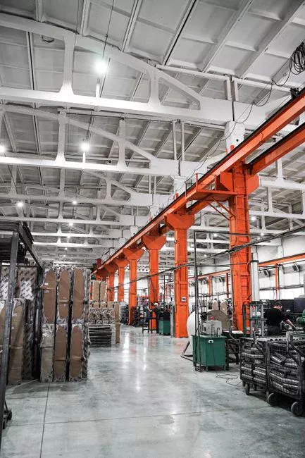
The hybrid train is the right answer for most Meridian stamping and machining shops with both an oil and a solids problem. The typical flow path is: equalization (buffer the press-dump slugs) → chemical conditioning (coagulant + flocculant dosing) → DAF for oil, grease, and floatable solids → lamella clarifier for carryover TSS and metal hydroxide precipitates → pH adjust / polish → discharge. A DAF added ahead of an existing clarifier that is running past its solids capacity is often the cheapest way to buy headroom without rebuilding the plant (per S5). For plants pursuing water reuse downstream of the DAF + clarifier train, an MBR integrated wastewater treatment stage can polish the effluent, but only after the bulk oil and TSS are removed — membranes do not tolerate tramp oil or metal fines. If your weekly wastewater characterization shows both >100 mg/L oil & grease and >200 mg/L TSS on the same day, plan for both stages.
2026 Cost and Compliance Reality for a Meridian Metals Plant
Directional cost framing for a 2026 budget:
- CAPEX: A packaged clarifier is the lower-cost entry point. A DAF system costs more upfront because of the compressor, saturator, recycle pump, and integrated control panel (per S3 and S5). Most Meridian shops spend CAPEX on both because the wastewater contains both fractions.
- OPEX: Clarifiers win on energy and consumables — no compressed air, modest polymer. DAF systems consume more power and polymer, but they remove oil to a level a clarifier cannot reach, which directly cuts POTW surcharges.
- Compliance anchor: EPA 40 CFR Part 433 sets the categorical pretreatment standards for metal finishing; local Meridian POTW limits typically tighten oil & grease, TSS, and individual metals. The technology must hit these numbers.
- Operational lever: A DAF is only as good as its coagulant and polymer dosing (per S5). An automatic chemical dosing skid is the best insurance against under-performing chemistry. Sludge from either separator should be dewatered with a plate and frame filter press to cut hauling volume — typically 75-85% moisture reduction.
Frequently Asked Questions
Should a Meridian fabricated metals plant install a DAF or a clarifier first?
If the dominant load is free oil, tramp oil, and emulsified coolant, install the DAF first — it hits ~95% oil and grease removal versus ~70% for a clarifier on the same conditioned stream (per S1). If the dominant load is grinding swarf and metal fines, start with a lamella clarifier, which can cut solids by ~90% at lower CAPEX. If both fractions are present, run them in series: a DAF system ahead of a lamella clarifier handles oil and TSS in one train.
Can a DAF system replace a clarifier in a metal stamping or machining shop?
For a stamping or machining line with both tramp oil and metal fines, no — a DAF alone typically removes 70-85% of settleable solids (per S3) compared to ~90% for a clarifier (per S1). For oil-dominated streams with low TSS, a DAF can replace a clarifier entirely. The hybrid DAF-then-clarifier configuration is common in Meridian because the wastewater carries both fractions (per S1).
What oil and grease and TSS limits do Meridian metals plants have to meet?
EPA 40 CFR Part 433 sets categorical pretreatment standards for the metal finishing category, and local Meridian POTW limits typically tighten oil & grease, TSS, and individual metals (zinc, nickel, lead, chromium) beyond the federal floor. A correctly sized DAF plus lamella clarifier with proper chemical precipitation is the standard train used to hit those numbers.
How do flow swings from press dumps affect DAF vs clarifier performance?
DAF tolerates oily shock loads better because the microbubbles attach to fresh emulsified oil within minutes in a single cell (per S5). A clarifier tolerates sustained high TSS better because of its sludge storage volume, but it lags a sudden oily slug. Equalization upstream of either unit — typically 8-24 hours of retention — smooths the spikes so either separator runs