

Why Pharmaceutical Wastewater Breaks Generic Clarifier Designs
A secondary clarifier in a pharmaceutical plant must absorb slug loads of solvents, mother liquors, and clean-in-place (CIP) rinse that municipal designs never see. Generic clarifier sizing rules drawn from publicly owned treatment works (POTW) assume a continuous, biodegradable feed with BOD₅ between 150-300 mg/L and TSS between 200-400 mg/L, where a 50-65% TSS removal at the primary step is a reasonable expectation (per Fehr Graham, municipal clarifier reference). Pharma primary clarifiers typically remove only 30-50% of TSS because emulsified APIs, residual organic solvents, and silicon-based antifoams resist gravity settling and pass straight into the biological reactor. When those compounds reach the activated-sludge basin, they shock the biomass: API residuals and residual solvents inhibit nitrifiers and floc-formers, the sludge volume index (SVI) drifts above 150 mL/g, and the clarifier's solids capture collapses within hours.
Operating variability is the second reason municipal rules fail pharma. Batch reactor discharges from synthesis suites arrive in 2-4 hour slug windows; CIP rinses arrive at 50-60 °C with pH between 1 and 13; antibiotic fermentation broths hold residual beta-lactams at 5-50 mg/L that suppress heterotrophs downstream. Field data from API/finished-dose plants shows influent pH swings of 5-9 within a single shift, temperature swings of 20-38 °C between batch and cleaning cycles, and total dissolved solids (TDS) from API synthesis salts pushing conductivity above 8,000 µS/cm (HydropureWater field data, 2026). Under those conditions, the sludge blanket is no longer the stable 1-3 ft layer municipal designers assume; it can rise, fall, or invert within a single shift. Borrowing a POTW clarifier datasheet into this duty is a documented path to failed batch validation and discharge excursions. The engineering basis for the secondary clarifier working principle guide assumes a much narrower envelope than a pharma line actually delivers.
Pharma Secondary Clarifier Sizing Parameters
Surface overflow rate (SOR) of 18-28 m³/m²·d is the working range for a pharma activated-sludge clarifier, and it is tighter than the 30-40 m³/m²·d band that municipal references cite for secondary units. Holding SOR at the low end of the pharma range protects against the short-circuiting that batch dumps cause, and it leaves hydraulic headroom for the 1.5-2.0× peak factor that CIP surges impose. Mixed liquor suspended solids (MLSS) should be designed for 2,500-4,500 mg/L in a conventional activated-sludge train; if a membrane bioreactor (MBR) sits upstream, the downstream clarifier (acting as a polishing/sludge-thickening step) must handle 5,000-8,000 mg/L without blanket washout. Hydraulic retention time (HRT) of 2-3 hours at average dry-weather flow is the published design target, but the peak-factor check matters more: a clarifier sized for 2.5 h HRT at average flow drops to 1.0-1.2 h during a CIP peak, which is below the 1.5 h threshold where scum and dispersed solids carry over the weir.
Weir loading rate must stay at or below 250 m³/m·d to contain the foaming events that antibiotic-producing lines generate, and a peripheral V-notch weir on a circular unit outperforms a single straight weir on rectangular flights. Side water depth (SWD) of 4.3-5 m is the minimum published threshold to prevent sludge blanket washout during hydraulic peaks (per Fehr Graham); pharma plants should design to the upper end of that range when land allows. Return activated sludge (RAS) rate is set at 50-100% of influent flow, with waste activated sludge (WAS) pulled at 0.5-1.5% solids and routed to a downstream dewatering unit. The numbers below are the typical 2026 pharma design range a process engineer should copy into the clarifier datasheet and the P&ID; they are the envelope a QbD reviewer will accept on first read.
| Parameter | Pharma design range (2026) | Municipal reference (Fehr Graham) | Driver |
|---|---|---|---|
| Surface overflow rate (SOR) | 18-28 m³/m²·d | 30-40 m³/m²·d | Batch CIP peak-factor headroom |
| MLSS (conventional AS) | 2,500-4,500 mg/L | 2,000-3,500 mg/L | API/solvent inhibition margin |
| MLSS (post-MBR polish) | 5,000-8,000 mg/L | N/A | MBR upstream; clarifier acts as thickener |
| HRT at average flow | 2-3 h | 1.5-2.5 h | Foam/scum carryover control |
| Weir loading rate | ≤250 m³/m·d | ≤375 m³/m·d | Antibiotic-foam containment |
| Side water depth (SWD) | 4.3-5.0 m | 3.5-4.3 m | Sludge blanket stability |
| RAS rate | 50-100% of Q | 25-75% of Q | Higher MLSS turnover, lower SVI risk |
| WAS solids | 0.5-1.5% | 0.5-1.0% | Filter-press feed target |
Effluent Targets and Regulatory Anchors for Pharma Clarifiers
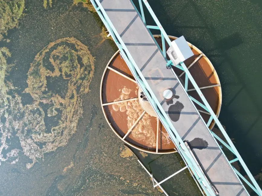
A pharma secondary clarifier should deliver TSS below 30 mg/L and BOD below 30 mg/L as the routine operating point; that envelope satisfies EPA 40 CFR Part 438 categorical pretreatment standards for the Pharmaceutical Manufacturing point source category and most state pollution control board (PCB) limits for discharge to a municipal sewer. Plants sending clarified effluent to cooling-tower makeup or boiler feed need a tighter target of TSS below 10 mg/L, and that number is not reachable from the clarifier alone — a downstream multimedia filter, ultrafiltration, or a brackish-water RO polish is required, and the sizing for that downstream step is documented in the engineering guide for brackish-water RO design criteria for 2026. Antibiotic residues measured as total organic carbon (TOC) or as specific API markers should appear in the QA sampling plan for the clarifier overflow, not only on the influent side; a clarifier is not designed to remove dissolved APIs, and a rising effluent TOC is the first signal that the upstream biological stage is failing to oxidize them.
The clarifier itself is not named in FDA process water guidance, WHO TRS guidance, or EMA Annex 1, but the equipment envelope it sits inside is. GMP documentation typically stops at the bioreactor and resumes at the effluent polish, and the clarifier is treated as a utility — a misclassification that has caused validation gaps during FDA inspections. A defensible position is to document the clarifier's MLSS, SOR, and effluent SS as critical process parameters (CPPs) inside the same QbD framework the bioreactor uses, even if the regulator does not require it. Above 4,500 mg/L MLSS in a conventional train, effluent SS rises non-linearly; lamella or DAF polish is required to hold the 30 mg/L TSS number, and a lamella retrofit inside a BNR-fed clarifier carries the design risk described in the next section.
| Stream | Pharma target (clarifier effluent) | Regulatory anchor | Action if exceeded |
|---|---|---|---|
| TSS — discharge to sewer | <30 mg/L | 40 CFR Part 438; state PCB | Investigate blanket rise, RAS rate |
| TSS — cooling-tower reuse | <10 mg/L | Internal QA / EHS | Add multimedia filter or RO polish |
| BOD₅ — discharge to sewer | <30 mg/L | 40 CFR Part 438; state PCB | Check upstream BNR performance |
| API markers / TOC | Trending, site-specific | EMA / FDA QbD | Flag biological-stage inhibition |
| pH | 6.5-8.5 | State PCB | Verify neutralization prior to clarifier |
Clarifier Configuration Choices for Pharma Plants
Circular center-feed clarifiers are the default choice for new API/finished-dose plants. The central feed well dampens batch hydraulic shocks by distributing flow radially, and the peripheral scum skimmer and beach handle antibiotic foaming better than rectangular chain-and-flight flights, which tend to push scum to one end and re-suspend it. Rectangular chain-and-flight clarifiers are still in service at older API sites with long, narrow layouts, and they are acceptable when paired with adequate influent buffering, but they are more sensitive to short-circuiting during a 4× batch surge and they require more operator attention to the flight speed and the scum trough.
Lamella / inclined-plate retrofits inside an existing secondary clarifier are a different proposition from a standalone lamella unit, and the difference is documented. Lee (2012) compared two parallel secondary clarifiers fed from the same BNR reactor — one with lamella plates inserted, the other without — and found that MLSS attached to the inclined plates, detached in clumps, and produced higher effluent SS than the non-lamellar unit at every MLSS concentration tested. The author concluded that lamella plates should not be inserted into a BNR-fed secondary clarifier and that the prior recommendation must be withdrawn (Lee, 2012, Journal of Korean Society of Water and Wastewater, 26(3), 471-478). For a pharma plant considering an in-tank retrofit, the Lee finding means a pilot test on plant liquor is mandatory, not optional. A standalone high-efficiency sedimentation tank is a separate piece of equipment that uses inclined plates in a controlled upflow geometry, and surface loadings of 20-40 m/h are achievable; the engineering tradeoffs and selection criteria are covered in the lamella clarifier engineering guide, and the equipment itself can be sourced as a high-efficiency lamella clarifier for greenfield API lines. Dissolved air flotation is paired with the secondary clarifier for emulsified API and oil-bearing streams; a DAF system downstream of the clarifier polishes dispersed solids and oils that the clarifier cannot capture, but it is not a replacement for the clarifier.
| Configuration | Hydraulic tolerance | Foam/scum handling | Footprint | Pharma fit |
|---|---|---|---|---|
| Circular center-feed | Good (radial damping) | Excellent (peripheral skimmer) | Larger diameter, lower profile | Preferred for greenfield |
| Rectangular chain-and-flight | Moderate (short-circuiting risk) | Moderate (single scum trough) | Long, narrow | Acceptable with influent buffer |
| Lamella retrofit (in-tank) | Reduced (Lee 2012 finding) | Reduced (detached MLSS) | Same tank | Pilot-test mandatory |
| Standalone lamella (HES tank) | Good (20-40 m/h loading) | Good | Small footprint | Polish step or primary |
| DAF downstream of clarifier | Good for emulsified oil | Excellent | Compact | Polish step, not replacement |
Operating the Pharma Secondary Clarifier Within the GMP Envelope
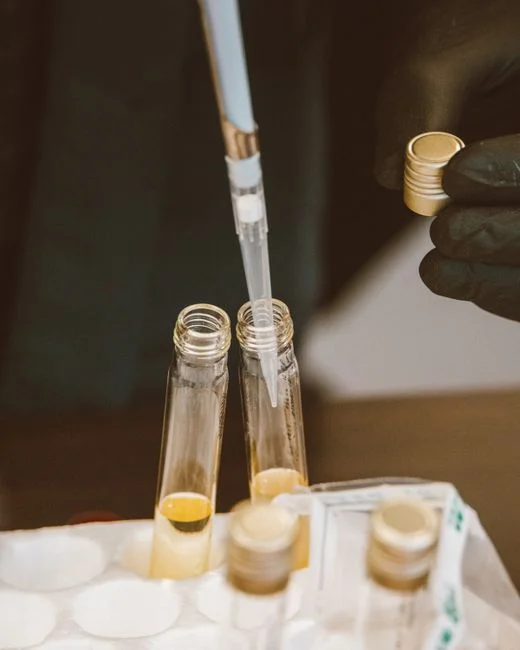
The clarifier is a process step, not a utility afterthought, and it should be documented in the QbD dossier with the same discipline as the bioreactor. Define the critical process parameters (CPPs) as SOR, MLSS, RAS rate, sludge blanket depth, and weir loading; trend them on the PI batch record at the same frequency as the bioreactor DO and pH. Sludge blanket depth should be trended continuously with a suspended-solids probe or by a manual core sample at least once per shift on antibiotic lines, where bulking episodes and rising SVI are routine. WAS should be pulled to a defined cake-solids target so the upstream plate and frame filter press is not overloaded; the 0.5-1.5% range is the typical feed concentration, and an automatic chemical dosing system for polymer conditioning ahead of the press keeps the cake at 22-28% dry solids.
CIP residues must be diverted to a neutralization tank before the clarifier; a hot CIP slug at pH 1 or 13 sent directly into a biological clarifier will collapse the sludge blanket inside one shift. Alarm setpoints should be defined and tested: rising sludge blanket above the design SWD triggers a WAS pull and a RAS rate increase; falling RAS suspended solids below 4,000 mg/L triggers a check for sand or grit carryover from the primary; rising effluent turbidity above the site alarm triggers a halt of batch discharges upstream and an SOP-driven investigation. Treat each alarm as a deviation that lands in the same review queue as a bioreactor pH excursion, because the regulatory consequence of an undocumented clarifier failure is the same.
Frequently Asked Questions
What is the typical surface overflow rate for a pharma secondary clarifier?
The typical SOR for a pharma secondary clarifier is 18-28 m³/m²·d, tighter than the 30-40 m³/m²·d range used for municipal designs. The lower bound protects against the 1.5-2.0× peak factor that batch CIP discharges impose on a pharma train.
Can lamella plates be retrofitted into a pharma secondary clarifier?
Lamella plates should not be inserted into a BNR-fed secondary clarifier without a pilot test on plant liquor. Lee (2012) compared two parallel clarifiers from the same BNR reactor and found that detached MLSS from the inclined plates caused higher effluent SS than the non-lamellar unit at every MLSS concentration tested, and the original recommendation to retrofit was withdrawn.
What MLSS range should a pharmaceutical secondary clarifier handle?
Design for 2,500-4,500 mg/L MLSS in a conventional activated-sludge train, and up to 5,000-8,000 mg/L when a membrane bioreactor sits upstream and the clarifier is acting as a polishing or sludge-thickening step. Above 4,500 mg/L in a conventional train, effluent SS rises non-linearly and a lamella or DAF polish is required to hold the 30 mg/L TSS target.
What effluent TSS should a pharma secondary clarifier deliver?
For discharge to a municipal sewer under 40 CFR Part 438, target TSS below 30 mg/L and BOD below 30 mg/L. For cooling-tower makeup or boiler-feed reuse, target TSS below 10 mg/L, which requires a downstream multimedia filter or brackish-water RO rather than a tighter clarifier.
How does a pharma clarifier differ from a municipal one?
A pharma clarifier must tolerate batch solvent spikes, pH swings of 5-9, antibiotic-driven biomass inhibition, and temperature swings of 20-38 °C between batch and cleaning cycles, while holding effluent TSS below 30 mg/L. A municipal design assumes continuous, biodegradable feed and a 50-65% primary TSS removal, neither of which holds in a pharma line.