Why Agricultural Chemicals Wastewater Doesn't Fit a Standard DAF-vs-Clarifier Rule
For agricultural chemicals wastewater in Townsend, USA in 2026, choose a Dissolved Air Flotation (DAF) system when the stream carries emulsions, oils, surfactants, or colloidal pesticide carriers — DAF routinely delivers 90–95% FOG and 70–85% TSS removal using 30–50 µm microbubbles. Choose a clarifier when the dominant load is settleable inorganic solids or settleable catalyst fines with low oil content, where 85–90% TSS removal at lower CAPEX is acceptable. Most agrochemical plants use a hybrid train: DAF first, then a lamella clarifier polishing step.
The generic "DAF for oil, clarifier for solids" decision rule that shows up in vendor whitepapers breaks down on an agrochemical site because the wastewater signature is not a single stream — it is a four-stream mixture. Formulation washwater carries emulsified active ingredients at 200–2,000 mg/L FOG and 500–3,000 mg/L TSS. Equipment-CIP (clean-in-place) streams run hot (40–60 °C), low-pH (1.5–3.0), and high in chloride, which limits materials of construction. Batch tank bottoms arrive as slugs of 5–20% solids over a 15–60 minute window, often 3–5× the daily-average flow. Cooling-tower and boiler blowdown contributes dissolved solids and trace metals that neither DAF nor a clarifier is designed to address, but it dilutes the organic load in the equalization basin.
Emulsified pesticide carriers, surfactant-stabilized actives, and intermittent slug loads defeat a simple gravity clarifier because the flocs are low-density and partially buoyant — they drift across a clarifier rather than settling. A clarifier's surface overflow rate of 1–2 m/h cannot capture colloids in the 5–50 µm range. The Townsend-specific dimension is the discharge pathway: a facility that discharges through the local POTW (Townsend-area municipal authority) under a Delaware DNREC pretreatment permit faces local limits on FOG (typically <100 mg/L), sulfides, and pH, plus Chesapeake Bay watershed scrutiny on total nitrogen and total phosphorus — any of which can force a DAF into the train regardless of how "settleable" the solids look on a jar test.
EPA 40 CFR Part 455 is the controlling effluent guideline for pesticide formulating, packaging, and repackaging facilities and shapes both technology selection and monitoring frequency. The Part 455 framework also requires zero discharge of process wastewater from some active-ingredient operations, which is why a robust primary solids/emulsion removal step (DAF or hybrid) is non-negotiable for the 2026 CAPEX cycle.
How DAF and Clarifiers Actually Separate Contaminants
DAF works by saturating a pressurized recycle stream (typically 20–30% of the throughput) with air at 4–6 bar, then releasing that pressure through needle valves or nozzles at the bottom of the flotation cell. The pressure drop generates a cloud of 30–50 µm microbubbles that attach to chemically conditioned floc particles and lift them to the surface at rise rates of 5–20 m/h, where a paddle skimmer scrapes the float into a sludge hopper. Heavier settleables drop to a cone bottom and are augered out separately. The design rise rate is governed by the air-to-solids ratio (A/S, mass of air released per mass of solids treated) and saturation pressure, per the EPA Process Design Manual: typical A/S for chemical-industry sludge is 0.02–0.06, with higher A/S reserved for streams carrying a high fraction of light, low-density colloids. A practical reference for the full hydraulic train is the DAF system process flow diagram walkthrough.
A clarifier separates contaminants by gravity, governed by Stokes' law (terminal settling velocity proportional to the square of particle diameter and the density difference between particle and water). Conventional circular or rectangular clarifiers are sized on surface overflow rate, not hydraulic retention time, because what limits performance is the cross-sectional area available for settling — not how long the water sits in the tank. A lamella clarifier stacks inclined plates at 55–60° inside the tank, multiplying the effective settling area by 5–10× and pushing surface loading rates to 20–40 m/h versus 1–2 m/h for a conventional clarifier, which is why the lamella geometry dominates new agrochemical clarifier installations.
The mechanical intuition that matters for technology selection: DAF pulls particles out of the water column by attaching bubbles; a clarifier waits for particles to fall out under gravity. Buoyant emulsions, oils, and surfactant-stabilized colloids cannot fall — they need a bubble to ride on. Dense mineral solids, catalyst fines, and lime precipitation sludges are denser than water and settle readily; they do not benefit from a bubble. That asymmetry is the entire basis of the decision matrix in the next section. For the full lamella clarifier design basis, the HydropureWater lamella clarifier product specification lists 60–80% footprint reduction versus a conventional clarifier of equivalent capacity, and a typical DAF system covers 4–300 m³/h in a single skid.
Side-by-Side Comparison: DAF vs Clarifier for Agrochemical Streams
The table below is the working comparison a procurement engineer should screenshot and circulate. Removal bands are drawn from vendor data published in 2026; mechanical and footprint values are typical for packaged units in the 50–500 m³/h range.
| Parameter | DAF system | Lamella clarifier | Conventional clarifier |
|---|---|---|---|
| Removal mechanism | Microbubble attachment (30–50 µm) and float | Stokes-law settling on inclined plates | Gravity settling on tank floor |
| FOG removal band | 90–95% | 50–70% | 50–65% |
| TSS removal band | 70–85% | 80–90% | 85–90% |
| Hydraulic tolerance (peak:avg) | Up to 3:1 without equalization | <1.5:1 preferred, equalization strongly recommended | <1.5:1, equalization required |
| Footprint per m³/h | 0.3–0.6 m² | 0.2–0.4 m² | 1.0–2.0 m² |
| Chemical demand | Coagulant (alum/FeCl₃) + flocculant (anionic or cationic polyacrylamide) | Flocculant only, lower dose | Flocculant only, lowest dose |
| Standard materials | 304SS; 316SS or polypropylene for chloride/solvent/low-pH | 304SS/FRP; 316SS optional | Concrete + 304SS launderers |
| CAPEX band (50–500 m³/h) | $120–800K | ~50–70% of equivalent DAF | ~30–50% of equivalent DAF |
| OPEX driver | Polymer 60–70%, compressed air 15–20%, power 10–15% | Polymer 70–80%, sludge handling 15–20% | Sludge handling 50–60%, polymer 30–40% |
| Operator skill | Moderate (jar-test calibration, A/S tuning) | Low–moderate | Low |
Two points on the table are worth engineering commentary. First, the 3:1 peak:average hydraulic tolerance of DAF matters more than the headline removal numbers at an agrochemical site: a batch tank dumped over 30 minutes can deliver 4× the daily-average flow to the treatment train, and a clarifier without equalization will simply pass the slug through with no removal at all. Second, the materials row drives more retrofits than any other line. Standard 304SS handles most formulation washwater, but any stream with >200 mg/L chloride, any low-pH (<3) CIP wash, or any aromatic solvent exposure should be specified in 316SS or polypropylene (per SigmaDAF 2026 published options). The 316SS premium is typically 25–40% on the tank and skid, but it is a one-time cost — chloride stress-corrosion cracking on 304SS is a 3–5 year failure mode in the worst cases.
Selection Matrix: Which Technology Fits Your Townsend Wastewater
This matrix is the working tool for the article. Map your real influent numbers against the row that fits, then read across to the technology recommendation. Thresholds are drawn from the comparison table above and from operating data at full-line pesticide formulators discharging to POTWs in the Chesapeake Bay watershed.
| Stream profile | Influent thresholds | Primary unit | Polishing step | Expected effluent FOG / TSS |
|---|---|---|---|---|
| High FOG, moderate TSS | FOG >200 mg/L, TSS 500–1,500 mg/L | DAF | None or sand filter | FOG <50 mg/L, TSS 50–150 mg/L |
| High settleable TSS, low FOG | FOG <50 mg/L, TSS >1,000 mg/L with mineral/catalyst fines | Lamella clarifier | None or media filter | FOG <30 mg/L, TSS 50–100 mg/L |
| High FOG + high TSS + variable pH (2–11) | FOG >200 mg/L, TSS >1,000 mg/L, batch pH swings | DAF with pH conditioning | Lamella clarifier | FOG <30 mg/L, TSS <50 mg/L |
| Brine / high dissolved solids | TDS >5,000 mg/L, FOG/TSS both low | Neither — route to evaporator or RO | n/a | n/a (managed by salt-rejection system) |
| POTW discharge path (Townsend default) | Local limit FOG <100 mg/L, sulfide control | DAF (mandated by local limit) | Lamella clarifier for TSS margin | FOG <50 mg/L, TSS <50 mg/L |
The hybrid DAF → lamella clarifier configuration is the 2026 standard for full-line pesticide formulators and packagers in this region. DAF first removes the buoyant load that would otherwise blind or float through a clarifier, then the lamella clarifier polishes the remaining settleable TSS to a level that meets typical POTW discharge limits of <50 mg/L TSS. The chemical conditioning step ahead of the DAF (coagulant + flocculant, jar-tested) does most of the heavy lifting; the lamella stage only needs light flocculant aid. A DAF vs clarifier for chemicals wastewater in Troy covers the same hybrid logic for a different chemical sub-segment, and the broader regulatory context is laid out in the pretreatment compliance guide for inorganic chemicals plants.
Cost Bands and 2026 CAPEX Orientation for the 50–500 m³/h Plant
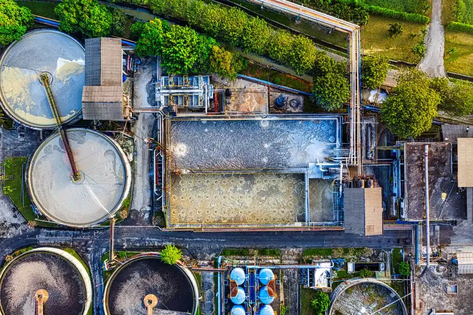
Order-of-magnitude CAPEX bands for packaged, skid-mounted equipment in 2026 USD: a DAF sized at 50 m³/h runs $120–180K, at 200 m³/h $280–420K, and at 500 m³/h $550–800K. A lamella clarifier at the same flow is roughly 50–70% of the comparable DAF CAPEX. The hybrid DAF + lamella clarifier train adds 20–35% to single-technology CAPEX, but it typically lowers lifetime chemical cost because the DAF removes the colloidal load that would otherwise force very high flocculant doses on the clarifier to achieve the same effluent quality.
OPEX for DAF is dominated by polymer/coagulant (60–70% of OPEX) and compressed air for the saturator (15–20%); power consumption is 0.3–0.6 kWh/m³ treated. A lamella clarifier draws 0.05–0.15 kWh/m³ — substantially less — but it generates more sludge by mass because it does not concentrate float as effectively as a DAF, so sludge handling can flip the OPEX comparison depending on dewatering cost. Site-specific cost varies with materials of construction (316SS premium 25–40%, polypropylene premium 15–25%), automation level (PLC with online TSS vs manual jar-test-based dosing), and US Northeast installation labor rates, which run 15–25% above the 2026 national average for mechanical and process piping. Polymer consumption typically lands at 2–10 mg/L for the DAF stage and 0.5–3 mg/L for the lamella stage, jar-test dependent; an automatic chemical dosing system paired with online streaming-current or TSS sensors is the standard 2026 control approach to keep that number at the bottom of the band.
Five-Step Selection Protocol for a 2026 Townsend Agrochemical Plant
Step 1. Characterize the wastewater with 5–7 days of composite sampling across all shift patterns. Capture FOG (EPA 1664 HEM), TSS (SM 2540D), COD (SM 5220D), pH, temperature, and instantaneous flow. A slug from a batch tank dump will not show up in a single daily composite — use auto-samplers triggered on flow or pH.
Step 2. Confirm the discharge pathway. POTW pretreatment under a Delaware DNREC permit triggers local FOG, sulfide, pH, and metals limits that usually mandate DAF regardless of the influent profile. Direct surface-water discharge under a Delaware NPDES permit brings Chesapeake Bay watershed nutrient scrutiny (TN, TP) that affects downstream biological treatment sizing, not the primary solids step, but it changes the design margin you carry through the train.
Step 3. Plot the FOG and TSS numbers from Step 1 onto the selection matrix above. The row that matches dictates the primary unit; the polishing step is usually free if you stayed inside one technology band, mandatory if you crossed into the hybrid band.
Step 4. Pilot a DAF on a slip stream (1–5 m³/h) if FOG is >200 mg/L, and run jar tests in parallel to fix coagulant and flocculant type and dose before any vendor RFQ. Pilot data plus jar tests on actual plant wastewater are the only defensible basis for sizing — vendor-provided removal curves are not a substitute for site-specific confirmation.
Step 5. Lock the design basis before going to RFQ: peak:average ratio (use 3:1 if batch-driven), turndown (typically 4:1 for a DAF, 2:1 for a lamella), materials of construction (default 304SS, upgrade to 316SS or PP for any chloride, solvent, or <3 pH stream), and automation scope. The DAF system covers 4–300 m³/h and the lamella clarifier line scales to similar envelopes; pair the selection with a DAF system process flow diagram walkthrough to confirm hydraulics before signing a PO.
Frequently Asked Questions
Can a DAF or a clarifier handle the hydraulic surges from a batch agrochemical plant?
DAF handles 3:1 peak-to-average surges without equalization, which is the common case at batch agrochemical sites where a reactor dump or CIP cycle hits the treatment train as a 30–60 minute slug. Clarifiers prefer <1.5:1 peak:average and need an equalization basin upstream to absorb the rest. For a comparable comparison in a different sub-segment, see the DAF vs clarifier for mining wastewater case where surge loads are also the deciding factor.
Is a hybrid DAF + lamella clarifier configuration standard for pesticide formulators in 2026?
Yes. A DAF followed by a lamella clarifier is the 2026 standard train for full-line pesticide formulators and packagers, and it aligns with EPA 40 CFR Part 455 expectations for primary solids and emulsion removal ahead of any biological or advanced polishing step. The DAF takes out the buoyant load; the lamella clarifier polishes settleable TSS to typical POTW limits of <50 mg/L.
Which technology actually removes emulsified pesticide carriers and surfactant-stabilized actives?
DAF. Pesticide carriers and surfactant-stabilized emulsions have densities close to or below water, so they drift across a clarifier rather than settling. DAF microbubbles (30–50 µm) attach to the flocculated droplets and float them to the surface for skimming. Removal bands of 90–95% FOG are typical with proper coagulant/flocculant conditioning, versus 50–70% on a lamella clarifier for the same stream.
What materials of construction should I specify for agrochemical wastewater?
Default to 304SS for formulation washwater with no chloride, no solvent, and pH >3. Specify 316SS for any chloride >200 mg/L, any aromatic solvent exposure, or any sustained pH <3. Specify polypropylene (PP) or fiber-reinforced plastic (FRP) for the most aggressive CIP streams where both chloride and low pH are present. The 25–40% 316SS premium is a one-time cost; chloride stress-corrosion cracking on 304SS is a 3–5 year failure mode in the worst cases.
Should I rely on vendor removal curves when sizing a DAF for an agrochemical site?
No. Vendor curves are useful for screening, not for sizing. Run a 5–7 day composite sampling campaign and a jar test program to fix the actual coagulant and flocculant type, dose, and resulting floc strength, then pilot a DAF on a 1–5 m³/h slip stream at site temperature and pH. The pilot result plus the jar test is the only defensible basis for a CAPEX-grade sizing — anything else is a budget number, not an engineering number.