
Why the Iron Range Changes the Pretreatment Math
A fab sited near Hibbing, MN does not run a sewer-pretreatment math problem that can be solved with a Phoenix or Chandler template. The receiving Iron Range wastewater authority is typically a small Water Pollution Control Plant (WPCP) serving tens of thousands of residents, not the million-plus catchment of a Sun Belt metro, and its Sewer Use Ordinance (SUO) — not 40 CFR Part 413 — sets the binding number at the discharge manhole. That distinction is what makes the local delegation a project driver rather than paperwork.
The reference design case for a single Iron Range fab is a discharge envelope of roughly 0.5–3 MGD, drawn against a federal categorical floor that assumes an up to 10 MGD process-water demand at large logic fabs (per IDE Technologies, 2026). Even at the lower end of that envelope, mass load drives the train: 76% of water withdrawn by a fab is used in the manufacturing process itself, so pretreatment equipment is sized to the design-day pollutant mass, not the average flow (per Manufacturing Dive, citing ASU's Paul Westerhoff). The arithmetic is set by what a single wet-etch batch dumps in over a 20-minute window, not by the 24-hour average.
Cold-climate operations add a second binding constraint. Equalization basins, pH probes, and chemical dosing lines on the Range must be heat-traced and enclosed because CaF₂ settle behavior degrades below 10 °C, and winter influent temperatures push viscosity high enough to upset lamella and DAF performance. The 2024–2025 MPCA PFAS rulemaking trajectory sharpens the third constraint: scrubber blowdown routed to a small WPCP is now a permitting data point the MPCA will scrutinize, and routing that stream through on-site polishing rather than the headworks is becoming a default expectation rather than an option. For comparable categorical-industry context, see our pretreatment compliance reference for a comparable categorical industry.
The Three-Layer Regulatory Stack: 40 CFR 403, 40 CFR 413, and the Local SUO
The federal anchor is 40 CFR Part 403, the General Pretreatment Regulations, which establish the Industrial Pretreatment Program (IPP) framework, the Significant Industrial User (SIU) and Categorical Industrial User (CIU) permitting thresholds, Best Management Practices duties, and slug-control plan requirements (per EPA 40 CFR 403). 40 CFR Part 413 layers the semiconductor-specific categorical effluent limits on top of that framework and defines the minimum performance bar. The MPCA-delegated Sewer Use Ordinance sits on top of both and sets pH 5–11, oil & grease ≤100 mg/L, TSS typically near 250 mg/L, plus site-specific metals and fluoride targets at the discharge manhole (per HydropureWater field data, 2026).
Design rule: comply with the strictest of the three. On the Iron Range, the local SUO and the receiving WPCP's headworks tolerance almost always govern the design basis. The MPCA's NPDES/SDS pretreatment delegation means the state writes the enforcement envelope that the federal categorical floor only describes in the abstract — a small WPCP's biological capacity, not EPA's 40 CFR 413 numbers, defines what the fab is actually allowed to send down the manhole.
| Authority | What it sets | Typical binding parameters | Why it matters on the Iron Range |
|---|---|---|---|
| 40 CFR Part 403 (IPP) | Framework, SIU/CIU thresholds, BMPs, slug-control plan | Permit cycle, monitoring duties, accidental-release prevention | Defines the 5-year IPP permit cycle and DMR cadence the MPCA inspects against |
| 40 CFR Part 413 (categorical) | Semiconductor categorical effluent limits | Fluoride, metals, TSS ceilings at the categorical floor | Floor only; almost never the binding limit at a small POTW |
| Local SUO (MPCA-delegated) | Numerical limits at the manhole | pH 5–11; O&G ≤100 mg/L; TSS ~250 mg/L; site-specific F⁻, Cu, Ni, Cr | Binding ceiling in practice; sized to the receiving WPCP's headworks tolerance |
A PLC-controlled chemical dosing skid sized to local-SUO fluoride and metals targets — not the categorical floor — is the single most defensible capex line item on the project.
Stage 1: Source Segregation at the Piping Level
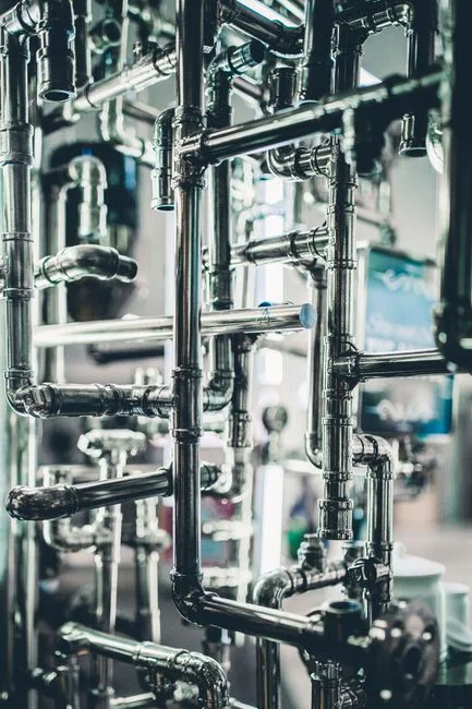
The first decision on a Hibbing-area pretreatment train is made at the P&ID stage, before any unit operation is selected. Fluoride-bearing streams from HF and NH₄F wet-etch and post-etch cleaning must be kept in dedicated piping, separate from CMP slurry waste and from TMAH/ammonia developer drains. The reason is pH: fluoride precipitates cleanly in the 6–8 range, metal hydroxides form in the 9–10.5 window, and TMAH biodegradation is fastest outside the fluoride window (per HydropureWater field data, 2026). Combine them and the operator is forced to dose toward a compromise pH, accept higher reagent consumption, and lose the ability to optimize any one line.
Segregation is a fab-design-time decision. Retrofits are rare because they require re-routing below-grade chemical drains, recertifying fire-seal penetrations, and rebalancing the equalization basin volume. Engineers who fail to specify segregated branches at the basis-of-design stage are committing the project to higher lifetime opex. A segregated collection system, each branch routed to its own treatment line, must be in place before any centralized recovery or discharge train is built.
Stage 2: pH Neutralization and Calcium Fluoride Precipitation
Stage 2 is the unit operation that almost always defines the reagent budget and the PLC architecture. Calcium chloride (CaCl₂) — or lime, Ca(OH)₂ — is dosed into the fluoride stream to drive precipitation of calcium fluoride (CaF₂), with a solubility product Ksp ≈ 3.9 × 10⁻¹¹. Sodium hydroxide or lime is dosed in parallel into the metal-bearing stream to drive metal hydroxides. The two streams then recombine into a single equalization basin ahead of solids separation.
Dose control is the heart of the system. A PLC-controlled automatic dosing skid with pH and fluoride ion-selective electrode (ISE) feedback holds reagent addition within ±5% of setpoint — the difference between meeting a 15 mg/L fluoride cap and exceeding it (per HydropureWater field data, 2026). Specify a 10:1 turndown ratio on the metering pumps and require the skid to accept both 4–20 mA flow-pacing and ISE feedback so the system rides out rinse-water spikes without overdosing caustic. Wet-etch fluoride influent routinely runs 50–500 mg/L; chemical precipitation brings it to single-digit mg/L before discharge, clearing common POTW ceilings of 10–25 mg/L and satisfying categorical limits set well below the 20–30 mg/L threshold that inhibits methanogenic activity in downstream anaerobic digesters.
The Stage 2 skid is the most defensible capex line item on the train, and the design parameters should be referenced against the PLC-controlled chemical dosing skid specification early in the basis-of-design memo.
Stage 3: Solids/Liquid Separation with DAF or Lamella

The precipitated CaF₂ and metal-hydroxide floc are removed in either a dissolved air flotation (DAF) system or a high-rate lamella clarifier. The decision between them is driven by three numbers: peak flow (m³/h), influent TSS after coagulation, and available bay footprint. An industrial DAF clarifier handles 4–300 m³/h at 4–25 m/h hydraulic loading and wins on high-flow, low-density, or oily streams — the right call for fluoride-rich etch streams and scrubber blowdown. A high-rate lamella clarifier delivers 20–40 m/h surface loading in a tighter footprint and is preferred when solids are denser and bay space is constrained.
Either device, when the upstream chemistry is correct, consistently delivers overflow TSS in the 30–60 mg/L range, clearing typical SUO ceilings. The decision rule for a Hibbing winter design is straightforward: DAF on the fluoride-bearing and scrubber branches where float loading is high, lamella on the metal-bearing branch where solids are denser and the building bay is tight. A rotary mechanical bar screen upstream of dosing protects pumps and DAF recycle from particulates, hair, and lint that ride in on utility-floor drains — a small line item with one of the highest ROIs on the train.
Stage 4: Polishing for Compliance and Reuse
The polishing step is what separates a compliance-only train from a water-stewardship train. For trace metals and hardness that escape precipitation, ion-exchange resin beds polish the effluent to single-digit µg/L on most parameters. For a fab with a documented reuse target, an industrial RO polishing system delivers 75–95% recovery per pass and drops TDS and residual fluoride to non-critical reuse grades suitable for cooling-tower makeup, scrubber feed, or non-process rinsing.
The selection rule is straightforward. For ≥50% recycle of the pretreatment effluent, an industrial RO is the right selection; for ≤50 m³/h polishing duty focused on trace metals and hardness, ion exchange is often the lower-capex path. A multi-media filter ahead of the RO holds the Silt Density Index (SDI) below 3 and protects the membranes — the standard pairing on fab RO pretreatment. RO permeate that is not reused is sewered well below any applicable limit, and the same skid serves both compliance and reuse duties. For process-specific polishing, see our CMP wastewater treatment by DAF reference.
Parameter Targets the Designer Should Hit at Each Stage
The table below is sized to be paste-ready into a PFD or a basis-of-design memo. Values are typical 2026 design targets for an Iron Range fab, not site-specific permit limits; site-specific values are set by the receiving WPCP and the MPCA-delegated SUO.
| Parameter | Influent range | After Stage 2 precipitation | After Stage 3 DAF/lamella | After Stage 4 polishing | Regulatory anchor |
|---|---|---|---|---|---|
| pH (fluoride line) | 1–4 | 6–8 | 6–8 | 6–8 | Optimal CaF₂ precipitation window |
| pH (metal line) | 2–5 | 9–10.5 | 9–10.5 | 7–9 (recombined) | Hydroxide precipitation window |
| Combined effluent pH | — | — | — | 5–11 | Local SUO envelope |
| Fluoride (mg/L) | 50–500 | <15 | <15 | Single-digit mg/L | Local SUO; 10–25 mg/L typical ceiling |
| Metals — Cu, Ni, Cr, Pb, Ag (mg/L, individual) | 5–50 | 1–3 | 1–3 | µg/L via ion exchange | 40 CFR 413 categorical; local SUO |
| Metals, combined (mg/L) | 20–100 | ≤5 | ≤5 | µg/L | Local SUO combined-metals cap |
| TSS (mg/L) | 200–1,000 | — | 30–60 | <10 (post-MMF) | Local SUO; SUO TSS ceiling ~250 mg/L |
| Oil & grease (mg/L) | 20–200 | — | ≤100 | — | Local SUO ≤100 mg/L |
| Sludge dry solids (cake) | 1–4% thickened | — | — | 25–35% cake | Off-site hazardous-waste disposal |
Solids removed in Stage 3 — CaF₂, metal hydroxides, and CMP residue — report as a thickened sludge at 1–4% dry solids and are dewatered in a plate-and-frame filter press sized from 1 m² (pilot) to 500 m² (full fab, multi-press line) to produce a 25–35% dry-solids cake for off-site hazardous-waste disposal. Filtrate returns to the head of the train.
Discharge vs Reuse: The Real Cost Decision on the Iron Range
The capex decision the CFO will actually sign off on is not "sewer or no sewer" — it is "sewer with pretreatment, or pretreatment with a partial-ZLD reuse train bolted on." Sewer discharge plus pretreatment carries opex dominated by CaCl₂, NaOH, sludge hauling, and IPP permit fees; off-site liquid hazardous-waste disposal runs 5–10× the per-m³ cost of sewer discharge (per 2025-09 industry benchmarks). Adding a 75–95% recovery RO polishing step turns the same pretreatment train into a water-stewardship asset, and state-of-the-art fabs recover 85–90% of pretreatment effluent through high-recovery RO, advanced filtration, and thermal polishing (per IDE Technologies, 2026).
Near-ZLD via brine concentrator plus crystallizer eliminates liquid discharge for the recovered fraction — the right answer when the receiving WPCP is capacity-constrained or when the MPCA tightens local limits under the 2024–2025 PFAS rulemaking trajectory. A chlorine-dioxide generator for on-site disinfection of the polished stream is the standard finishing step for any reuse duty, and pairing it with an industrial RO polishing system on the recovered fraction is the defensible 2026 reference configuration.
| Path | Typical capex envelope | Opex driver | Recovery / discharge | Decision trigger |
|---|---|---|---|---|
| Sewer discharge + pretreatment only | Lowest | CaCl₂, NaOH, sludge hauling, IPP fees | 0% recycle; 100% sewered | Receiving WPCP has headroom and the local SUO is stable |
| Sewer discharge + 75–95% RO polishing | Moderate (adds RO + MMF) | Membrane replacement, CIP chemicals, energy | 50–90% recycle; remainder sewered well below limits | Water-stewardship target; corporate net-positive commitments |
| Partial-ZLD (RO + brine concentrator + crystallizer) | Highest | Thermal energy, crystallizer maintenance | ≥95% recycle; minimal liquid discharge | WPCP capacity-constrained; MPCA tightening limits; PFAS trajectory |
Keeping the Permit: IPP Program, DMRs, and Online Monitoring
The IPP permit cycle runs 5 years and binds the fab to monthly Discharge Monitoring Reports (DMRs), routine POTW inspections (annually at baseline, more frequent for Significant Non-Compliance facilities), and a slug-control plan for accidental releases. Engineers who treat pretreatment as a permit-driven engineering program — not a black box bolted to the back of the fab — are the ones whose plants stay out of Significant Non-Compliance findings.
The minimum online monitoring package is a pH probe and a fluoride ion-selective electrode on the combined effluent header, plus an on-line ICP-OES or XRF for Cu, Ni, and Cr. Continuous monitoring delivers minutes of warning before a limit is exceeded — the difference between a clean DMR and an SNC finding. A PLC-controlled chemical dosing skid with closed-loop trim on pH, fluoride, and metals analyzers ties the regulatory duty directly to the unit operations, and every piece of equipment on the train must be backed by an SOP and a calibration record the POTW will inspect alongside the hardware.
Frequently Asked Questions
Which regulation actually governs a Hibbing-area fab's sewer discharge — federal or local?
The local MPCA-delegated Sewer Use Ordinance governs in practice, because 40 CFR Part 403 establishes the IPP framework, 40 CFR Part 413 sets the categorical floor, and the SUO enforced by the receiving WPCP sets the binding numerical limits at the manhole (per EPA 40 CFR 403; MPCA delegation). On the Iron Range, the SUO is sized to a small WPCP's headworks tolerance, not to a million-resident catchment.
What fluoride level can a fab realistically hit with calcium precipitation before sewer discharge?
Wet-etch fluoride influent of 50–500 mg/L is brought to single-digit mg/L by CaCl₂ or lime precipitation at pH 6–8, clearing common POTW ceilings of 10–25 mg/L and staying well below the 20–30 mg/L threshold that inhibits methanogenic activity in downstream anaerobic digesters (per HydropureWater field data, 2026).
Is source segregation really a fab-design-time decision?
Yes. Fluoride-bearing, CMP slurry, and TMAH/ammonia streams must run in segregated piping because their optimum treatment pH windows do not overlap — fluoride at 6–8, metal hydroxides at 9–10.5, TMAH biodegradation outside the fluoride window (per HydropureWater field data, 2026). Combining them forces a compromise pH and higher reagent consumption, and retrofitting segregation below-grade is rare and expensive.
How does the 2024–2025 MPCA PFAS rulemaking affect a fab's scrubber blowdown?
The 2024–2025 MPCA PFAS rulemaking trajectory turns scrubber blowdown routed to a small WPCP into a permitting data point the MPCA will scrutinize, and on-site polishing — high-pressure RO or NF followed by activated carbon or ion exchange, terminated by an AOP stage that mineralizes PFAS precursors — is becoming the default expectation rather than an option (per MPCA PFAS rulemaking, 2024–2025).