Why Houston Data Centers Need Dedicated Blowdown and Wastewater Treatment in 2026
A 2026 data center in Houston needs a two-lane treatment train: (1) a cooling-tower blowdown line targeting TCEQ Chapter 307 TPDES limits with hardness, silica, TDS, and Legionella control — typically side-stream softening, DAF for suspended solids, RO for TDS reduction, and ClO2 for biofilm — and (2) a sanitary/POTW lane using an MBR or package A/O plant. Reuse is driven by the same USGS finding that 25% of U.S. thermoelectric withdrawals already come from non-freshwater sources.
The macro signal has been visible for more than a decade. The USGS estimated that alternative water types already supplied approximately 25% of all U.S. thermoelectric withdrawals in 2010, most of it saline or brackish tidal water routed through once-through cooling systems (USGS SIR 2014-5148). That figure was a baseline, not a ceiling — it predates the hyperscale build-out now underway in the Texas Triangle. Freshwater demand for power and digital infrastructure has continued to climb, and reclaimed water for power plant cooling is now treated as an active engineering pathway rather than a future option (Diehl and Harris, 2014; OpenAlex, 2004).
Houston-specific drivers compress the timeline. Gulf Coast evaporation rates push cooling-tower cycles of concentration down unless blowdown is treated and recycled; the City of Houston and regional MUD pretreatment programs are tightening envelopes on TSS, BOD, and metals; and the I-45 corridor between downtown and The Woodlands is absorbing a dense cluster of new hyperscale campuses that cannot rely on potable expansion alone. In 2026, water is no longer a utility pass-through — it is a design constraint with a permit, a price, and a PUE line attached.
Cooling-Tower Blowdown Treatment: Chemistry, Limits, and Process Train
Cooling-tower blowdown is the most chemically loaded wastewater stream on a Houston data center campus, and it drives the unit-operation list. As cycles of concentration climb from 3 to 6+, the blowdown concentrates calcium, magnesium, silica, alkalinity, TDS, suspended solids from atmospheric dust and tower drift, and biological load from the cooling loop itself. Untreated, that stream will foul downstream membranes in days and feed Legionella and biofilm colonization in the reuse loop. TCEQ Chapter 307 TPDES limits and the City of Houston/MUD pretreatment envelope set the discharge ceiling; on-site reuse sets a tighter internal ceiling that has to be engineered to, not discovered.
The defensible five-step train for a 2026 Houston campus runs as follows:
- Sidestream softening — lime-soda or weak-acid cation exchange drops calcium, magnesium, and a portion of the alkalinity before the water reaches the RO. This step protects the membrane from hardness scaling and reduces the antiscalant dose downstream. Softener waste (the brine or lime sludge) is routed to a high-efficiency sedimentation tank for solids handling.
- Multimedia filtration — a multi-media filter as RO pretreatment knocks down turbidity and brings the Silt Density Index (SDI) into the range the RO membranes can tolerate, typically below SDI 5 and ideally below SDI 3 for thin-film composite elements.
- Dissolved air flotation — a DAF system for cooling-tower blowdown solids removal strips suspended solids, microbiological carryover, and metals precipitates when blowdown is blended with other plant waste streams such as airwasher or RO flush.
- Reverse osmosis — an industrial RO system for blowdown TDS reduction takes the blended stream from roughly 1,500–3,000 mg/L TDS down to a permeate suitable for cooling-tower makeup. Recovery is typically operated in the 75–85% band for blowdown duty; above 85% the concentrate becomes difficult to manage without advanced concentrate treatment.
- Chlorine dioxide — an on-site chlorine dioxide generator for cooling-loop biofilm control doses ClO2 into the reuse loop and the tower basin. Unlike chlorine, ClO2 does not form trihalomethanes at typical cooling-tower pH (7.0–8.5) and is effective against Legionella in biofilms at residual concentrations well below 1 mg/L.
The equipment envelope for the ClO2 step matters at campus scale. The generator range typically spans 50 to 20,000 g/h of equivalent ClO2, which covers a single 5 MW cooling plant up to a multi-building hyperscale campus running several thousand tons of cooling. Two-precursor generation (NaClO2 + HCl) is preferred over stabilized solutions because it avoids the long-term degradation and shipping classification issues of bulk chlorine dioxide.
For engineers who want a single view of the chemistry-to-equipment mapping, the table below is the version that goes into the design basis.
| Process Step | Target Contaminant | Typical Performance | Equipment |
|---|---|---|---|
| Sidestream softening | Ca, Mg hardness, partial alkalinity | Hardness reduction to <50 mg/L as CaCO3 | Lime-soda or WAC vessel |
| Multimedia filter | Turbidity, SDI | SDI < 5, turbidity < 1 NTU | Multi-media filter (sand, anthracite, garnet) |
| DAF | TSS, metals precipitates, biological carryover | TSS removal > 90% | DAF system, 20–40 m³/h·m² hydraulic loading |
| RO | TDS, silica, residual hardness | 75–85% recovery; permeate TDS < 50 mg/L | Industrial RO skid with FRP vessels |
| ClO2 | Biofilm, Legionella | 0.1–0.5 mg/L residual in basin | Two-precursor ClO2 generator, 50–20,000 g/h |
Sanitary and Process Wastewater: MBR vs. Package A/O for Houston Campuses
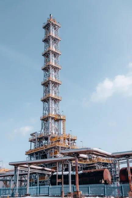
The sanitary and process wastewater lane is smaller in flow than the blowdown lane but tighter on permit risk, because it typically discharges to a MUD or to the City of Houston POTW interceptor. Two packaged unit operations dominate the 2026 shortlist for Houston campuses, and the choice between them is driven by footprint, reuse intent, and whether the effluent will ever touch the cooling-tower makeup system.
The first option is a packaged anaerobic/oxic (A/O) plant, exemplified by a WSZ underground A/O package sized for 1–80 m³/h with no full-time operator. It is the right pick for distributed facilities, guardhouses, and small admin buildings where the effluent is going straight to a MUD interceptor and reuse is not on the table. The second option is a membrane bioreactor (MBR), which combines activated sludge with ultrafiltration to deliver near-reuse effluent in a footprint roughly 60% smaller than a conventional activated-sludge plant of the same rating. For campuses that route any portion of the sanitary effluent back into cooling-tower makeup, toilet flushing, or landscape irrigation, an MBR skid for the sanitary sidestream is the better answer because the 0.1 μm flat-sheet membrane holds back the colloidal and bacterial load that a conventional clarifier would pass.
The building block for a campus MBR skid is the DF-series flat-sheet module with a 0.1 μm nominal pore and an integrated aeration box that provides the crossflow and scouring air in one vessel. The integrated aeration box cuts the air-blower count versus external scour systems and simplifies the CIP (clean-in-place) cycle, which matters when the operator on site is a facilities technician rather than a wastewater specialist. Both unit operations can meet typical Houston MUD and City of Houston POTW envelopes for BOD, TSS, and ammonia; the deciding factor is almost always reuse intent, not discharge compliance.
| Criterion | Package A/O (WSZ) | MBR (DF-series skid) |
|---|---|---|
| Flow range | 1–80 m³/h | 5–500 m³/h per skid, modular |
| Effluent BOD/TSS | < 20 / < 30 mg/L | < 5 / < 5 mg/L |
| Footprint | Standard | ~60% smaller than conventional |
| Reuse-ready | No (clarifier overflow) | Yes (0.1 μm membrane barrier) |
| Operator skill | Low (packaged) | Low–moderate (membrane CIP) |
| Best fit | Distributed / no-reuse sites | Hyperscale campuses with reuse intent |
Discharge vs. Reuse: The 2026 Decision Framework for Houston Operators
The end-of-pipe decision for treated blowdown in 2026 is a three-way branch, and the branch point is economic as much as regulatory. Option 1 is discharge to a MUD or the City of Houston POTW interceptor, which is the lowest-effort path but exposes the operator to industrial pretreatment surcharges, monthly volume limits, and any future restrictions the utility places on high-TDS streams. Option 2 is direct surface-water discharge under a TCEQ TPDES permit issued under 30 TAC Chapter 307, which sets numeric limits on TDS, TSS, chloride, sulfate, and several metals that have to be hit by the final treated stream, not by an intermediate. Option 3 is on-site reuse for cooling-tower makeup, landscape irrigation, or toilet flushing, which has the highest upfront capital cost but the lowest long-run OPEX once cycles of concentration are pushed to 5–6 or above.
The economic crossover moves toward reuse as cycles of concentration rise and as Houston's commercial water and wastewater rates continue to climb. At 5–6+ cycles of concentration on a hyperscale cooling plant, reuse typically beats POTW discharge on a 5-year OPEX basis because the avoided purchase of finished water and the avoided pretreatment surcharges compound against the membrane and pumping cost. The macro trend line reinforces that direction: the same USGS inventory that recorded 25% of U.S. thermoelectric withdrawals from non-freshwater sources in 2010 (USGS SIR 2014-5148) has been moving further toward reuse in every subsequent assessment, and reclaimed cooling water is now an established asset class in Texas water planning, not a pilot project.
| End-of-Pipe Option | Permit / Authority | Best When | Main Constraint |
|---|---|---|---|
| POTW / MUD discharge | City of Houston / MUD pretreatment | Low cycles, no reuse plumbing | Pretreatment surcharges, volume caps |
| Surface-water discharge (TPDES) | TCEQ Chapter 307 | No POTW nearby, large site | Numeric limits on TDS, Cl⁻, SO₄²⁻, metals |
| On-site reuse | TCEQ Chapter 210/290 reuse rules | Cycles ≥ 5–6, reuse plumbing in place | Capex for RO + ClO2, dual plumbing |
Equipment Mapping and 2026 Cost Perspective for a Houston Campus
The procurement-ready equipment list for the two-lane train fits on one page. The blowdown lane runs rotary bar screen → equalization basin → sidestream softener → multi-media filter → DAF → cartridge guard (5 μm) → RO skid → ClO2 generator → reuse storage. The sanitary lane runs screening → equalization → MBR (DF-series flat-sheet modules) → UV polish or low-dose ClO2 for the reuse sub-loop. The cross-cutting utility that ties both lanes together is the automatic chemical dosing system for pH trim, antiscalant feed to the RO, and biocide control; it is the lowest-cost line item on the equipment list and the one most often undersized in early-stage designs. Headworks protection starts with a rotary bar screen for headworks protection on the combined inlet, and the solids handling train typically ends at a plate-and-frame filter press fed from a high-efficiency sedimentation tank, with cake going off-site.
The 2026 cost view is dominated by two line items in different ways. Capex is dominated by the RO skid and the membrane modules — flat-sheet MBR modules and RO vessels are the most expensive single equipment packages on the bill of materials. Opex is dominated by pumping energy (the RO high-pressure pump is the largest single load), membrane cleaning chemicals, and the precursor chemicals for on-site ClO2 generation. Avoiding fabricated numbers: the only honest 2026 statement is that the unit operations named in this article are the ones the literature and field data converge on, and that the capital-vs.-operating split between membranes and chemical handling is the structural driver of lifecycle cost, not any single dollar figure.
Frequently Asked Questions
What ClO2 residual should we hold in the cooling-tower basin for Legionella control?
A residual of 0.1 to 0.5 mg/L free ClO2 in the basin, measured at the warm-water return, is the standard operating band for cooling-tower Legionella control under most ASHRAE 188 and TCEQ-aligned programs. An on-site two-precursor chlorine dioxide generator sized to the recirculation rate is the most reliable way to hold that band without the THM formation seen with free chlorine at cooling-tower pH.
What recovery rate should we target on the RO treating cooling-tower blowdown?
Plan for 75–85% recovery on a single-pass RO treating cooling-tower blowdown. Pushing above 85% is technically possible but the concentrate silica and hardness climb fast, and the antiscalant dose becomes a permit issue. The right recovery is the highest number the industrial RO system for blowdown TDS reduction can hold at stable scaling indices, not the maximum the membranes can survive for a week.
Where does treated blowdown go in Houston — POTW, TPDES, or reuse?
It depends on cycles of concentration and reuse plumbing. Below roughly 4 cycles, POTW discharge through a MUD or the City of Houston interceptor is usually cheapest. Above 5–6 cycles, on-site reuse for cooling-tower makeup typically wins on 5-year OPEX. Direct surface-water discharge under TCEQ Chapter 307 TPDES is the right answer only when no POTW interceptor is available and the site can hit the Chapter 307 numeric limits on TDS, chloride, and sulfate on the final effluent.
Can sanitary MBR effluent really be reused as cooling-tower makeup?
Yes, with a UF/MBR plus RO polish train, but the 0.1 μm flat-sheet MBR alone is not enough — the effluent is low in BOD and TSS, but it is still high in TDS and ammonia relative to cooling-tower makeup specs. The defensible configuration routes MBR permeate through a dedicated RO and ClO2 polish before it enters the cooling loop, which is also how AWS handles wastewater at hyperscale campuses and a similar approach is used in how Digital Realty treats wastewater at its data centers.
Related Equipment
- multi-media filter as RO pretreatment — specifications, capacity range, and technical data