Why AWS Built Its Hyperscale Water Strategy Around Reuse, Not Discharge
AWS targets Water+ Positive status by 2030, aiming to return more water to communities than its data centers consume. The program's 2021 Project Rainier case study in Oregon demonstrated municipal wastewater effluent routed into a cooling-tower makeup line, serving as a proof point for hyperscale direct potable-to-industrial reuse (per AWS Sustainability reporting, 2021). Because hyperscale campuses sit on 50–300 MW IT-load footprints, the daily water draw reaches 5,000–15,000 m³/day; permitting a discharge of that volume in a stressed basin is rarely practical. Economics and ESG commitments drive designs toward closing the loop. Each hyperscale campus separates its water balance into three discrete, metered streams treated and disposed of independently: (1) cooling-tower blowdown, which carries the highest dissolved load and is the primary target for on-site reuse; (2) sanitary or domestic sewage, a low-volume biological stream typically sent to a packaged plant; and (3) storm water plus non-contact process water (RO reject from non-cooling loops, humidification condensate, air-handling condensate), which is infiltrated, reused for irrigation, or banked as a Water+ offset. Operators should avoid blending these three streams in a single equalization tank, as the chemistry, regulatory class, and reuse destinations differ.
The On-Site Treatment Train AWS-Scale Campuses Use for Cooling-Tower Makeup
The five-step train converting raw makeup water into low-TDS, low-silica cooling-tower feed consists of coarse screening, lime/soda softening, dissolved air flotation, multi-media filtration, and reverse osmosis with chemical conditioning. Coarse screening followed by lime/soda softening drops calcium hardness from 250–400 mg/L as CaCO₃ to under 50 mg/L and strips most alkalinity, protecting downstream RO membranes from carbonate scaling. The process uses a skid-mounted DAF unit operating at a hydraulic surface loading of 20–40 m/h to float off metal hydroxides, silica precipitates, and entrained solids; a lamella clarifier can substitute where footprint is constrained. A multi-media filtration stage with anthracite, sand, and garnet polishes clarifier overflow to a Silt Density Index below 5 and turbidity under 1 NTU, meeting standard RO feed specifications. The industrial RO polishing stage pulls TDS from 500–1,500 mg/L down to under 50 mg/L and silica to under 5 mg/L, preventing irreversible silica scale on cooling-tower fill. Finally, a PLC-controlled chemical dosing skid manages corrosion inhibitors, oxidizing biocides, and pH trim, while a small side-stream softener polishes RO concentrate before recycling it into the cooling loop's blowdown stream.
Cooling-Tower Blowdown and Cycles of Concentration at AWS-Scale Campuses
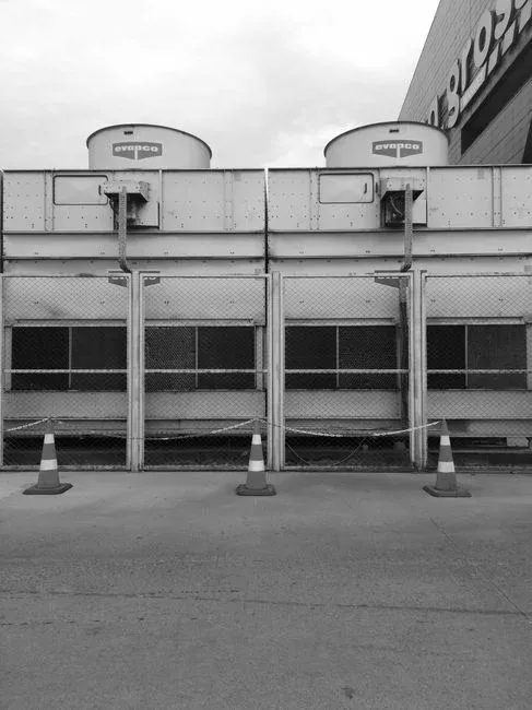
Cooling towers at hyperscale campuses typically run at 4–6 cycles of concentration (COC), concentrating dissolved solids 4–6 times relative to the makeup before a fraction is bled off as blowdown. At 4–6 COC, blowdown equals 1–3% of total makeup volume (per ASHRAE Guideline 188); a 100 MW IT-load campus with a 10,000 m³/day makeup demand generates 50–150 m³/h of blowdown, fitting within a skid-mounted DAF plus RO package. Blowdown chemistry drives the design: calcium hardness climbs to 400–800 mg/L as CaCO₃, silica to 40–150 mg/L, and TDS to 1,500–4,000 mg/L, alongside trace oxidizing biocides and trihalomethane precursors. A high-efficiency sedimentation tank with tube settlers upstream of the DAF can reduce clarifier footprint by 50–70% compared to conventional basins. The table below summarizes the parameter envelope for scaling this train to smaller sites.
| Parameter | Raw Makeup | After Softening + DAF + MMF | After RO (Cooling-Tower Feed) | Blowdown (4–6 COC) |
|---|---|---|---|---|
| Calcium hardness (mg/L as CaCO₃) | 250–400 | < 50 | < 5 | 400–800 |
| Silica (mg/L as SiO₂) | 20–60 | 15–40 | < 5 | 40–150 |
| TDS (mg/L) | 500–1,500 | 400–1,200 | < 50 | 1,500–4,000 |
| Turbidity (NTU) | 5–50 | < 1 | < 0.1 | 5–20 |
| SDI (15-min) | — | < 5 | < 3 | — |
Blowdown pH is maintained at 7.5–8.5 to keep silica soluble; an acid feed on the PLC-controlled chemical dosing skid trims excursions when cycles drift above 6 (HydropureWater field data, 2026).
Sanitary and Process Side-Streams: How Hyperscale Sites Keep Them Separate
Sanitary wastewater at a 100–300 MW campus runs 50–150 m³/day and is biologically distinct from cooling-tower blowdown—containing BOD (200–400 mg/L), ammonia (20–50 mg/L), and fecal coliform (10⁵–10⁷ CFU/100 mL)—requiring separate treatment. The standard solution is a buried WSZ A/O (anoxic/oxic) integrated sewage treatment plant for flows under 100 m³/day, or a containerized packaged MBR for sanitary side-streams for higher volumes, discharging to a subsurface drip field or municipal sewer. Process non-contact streams are segregated at the source for recycling to the cooling-tower makeup tank, landscape irrigation, or on-site reuse. Storm water is managed by retention/infiltration basins sized for the local 100-year, 24-hour storm event, with first-flush diversion as required (typical basin sizing: 0.5–1.0 acre-ft per 10 acres of impervious surface per NOAA Atlas 14). Maintaining hydraulic isolation between these streams prevents cross-contamination and ensures the packaged MBR operates independently of the cooling-tower DAF skid.
How the AWS Water+ Model Compares to a Mid-Size Industrial Wastewater Plant
The hyperscale water model provides a template for smaller sites, though scaling varies by IT load. A 100+ MW campus running 50–150 m³/h of blowdown justifies a full DAF-RO train due to the 3–5 year payback on water and sewer avoidance; a 1–10 MW edge site producing 5–20 m³/h of blowdown typically utilizes a DAF plus softener and chemical dosing program, limiting cycles to 3–4 to remain within silica solubility limits. The table below maps these operational differences.
| Design Element | Hyperscale (100+ MW, 50–150 m³/h blowdown) | Mid-Size Industrial (1–10 MW, 5–20 m³/h blowdown) |
|---|---|---|
| Primary softening | Lime/soda, continuous | Ion-exchange simplex or duplex |
| Clarification | DAF or lamella, 20–40 m/h | DAF or tube-settler, 15–25 m/h |
| Membrane step | Two-pass RO, 90–95% recovery | Single-pass RO or NF, 70–80% recovery |
| Cycles of concentration | 4–6 | 3–4 |
| Sanitary treatment | Packaged MBR, 50–150 m³/day | WSZ A/O buried plant, 5–30 m³/day |
| Biocide program | On-site ClO₂ generation, continuous | Slug-fed NaOCl, weekly |
| Water+ offset accounting | Full basin-level ledger | Site-level reuse only |
Mid-size operators can adopt side-stream softening to increase COC, utilize skid DAFs on cooling-blowdown lines to reduce TSS, and deploy packaged MBRs for sanitary streams. Technologies like 95% recovery RO loops and on-site ClO₂ generation remain exclusive to hyperscale operations. Regarding future compliance, the PFAS removal method comparison from 2025-08 details GAC, IX, and RO performance as several US states lowered PFAS action levels for surface discharge below 10 ng/L in 2025 (per EPA UCMR 5 reporting cycle).
Frequently Asked Questions
What is the main on-site wastewater treatment train at an AWS hyperscale campus?
Cooling-tower makeup is processed through lime/soda softening, dissolved air flotation, multi-media filtration, and reverse osmosis before chemical conditioning and reuse. Sanitary sewage is processed through a packaged biological plant (WSZ A/O or MBR), while storm water and non-contact process water are infiltrated or reused under the AWS Water+ framework.
How much cooling-tower blowdown does a hyperscale data center actually produce?
At 4–6 cycles of concentration, blowdown represents 1–3% of makeup volume. A 100 MW IT-load campus with approximately 10,000 m³/day makeup demand generates 50–150 m³/h of blowdown, which is manageable via skid-mounted DAF and RO packages.
Why doesn't AWS blend sanitary wastewater with cooling-tower blowdown?
Sanitary sewage contains BOD, ammonia, and fecal coliform that would foul RO membranes and violate industrial discharge permits. Hyperscale sites isolate these streams, treating sanitary flow via packaged MBR or buried A/O plants sized for 50–150 m³/day.
Related Equipment
- packaged MBR for sanitary side-streams — specifications, capacity range, and technical data