
Why Data Center Wastewater Is Now a Permit-Defining Issue
Singapore, Dublin, and Amsterdam imposed data centre construction moratoria between 2019 and 2022 specifically over water and grid stress, with Singapore's 2019 moratorium later tightened in 2022 to push operators toward low-water designs (per npj Urban Sustainability 2025, S2). The EU Energy Efficiency Directive (2023/1791) now mandates annual reporting of water consumption, WUE, and reuse KPIs for any data centre above 1 MW IT load, forcing every hyperscaler including Equinix to prove water reuse (per Energies 2025, S3). The strategic driver is the scale of the load: data centres consume 1–1.5% of global electricity, and EU data-centre electricity demand is projected to reach ~150 TWh by 2026, with cooling and IT processing accounting for roughly 80% of that draw (S3). Because cooling depends on water in most legacy IBX footprints, water-for-cooling is a permit-defining variable on par with power. Equinix reports a portfolio Water Use Effectiveness (WUE) and reports against the CEO Water Mandate, which puts reuse metrics under the same disclosure scrutiny as PUE and links them directly to investor ESG screens.
What Streams Actually Flow Through an Equinix Campus WW Plant
Cooling-tower blowdown represents the largest continuous wastewater stream at a typical Equinix IBX campus and is characterized by high total dissolved solids (often 1,500–5,000 mg/L), high calcium/magnesium hardness, silica in the 20–150 mg/L range, and residual scale-inhibitor and biocide chemistry. Adiabatic and humidification systems generate a second, more concentrated stream: reverse-osmosis reject with TDS often in the 10,000–30,000 mg/L band and very low flow—typically only 15–25% of RO feed volume. Sanitary sewage from offices and customer-space CRE is a third, smaller stream normally handled by a packaged MBR or sent directly to the municipal sewer; it does not pass through the industrial WW plant. Make-up water for indirect evaporative cooling and humidifiers is pre-treated by softener plus RO before entering the loop, so the reject from that RO acts as the primary feed to the on-site WW plant. Flow allocation follows a tight ratio: blowdown is roughly 1–2% of the cooling circulation rate, while RO reject sits at 15–25% of RO feed, necessitating an automatic chemical dosing for pH and anti-scalant control skid as a primary component of the train.
The Treatment Train Equinix-Style Campuses Actually Deploy
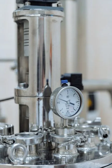
The packaged treatment train a hyperscale campus runs on cooling-tower blowdown and adiabatic RO reject is a six-step sequence that an industrial wastewater OEM would spec almost identically across sites. Step 1 is equalization and chemical dosing: blowdown is buffered in a holding tank and dosed with anti-scalant neutralizer, biocide quencher, and pH adjuster through an automatic chemical dosing skid to bring the chemistry into a controllable range. Step 2 is softening—typically lime/soda or weak-acid cation—to drop calcium, magnesium, and silica before the water hits the RO to prevent membrane scaling. Step 3 is a DAF unit for cooling-tower blowdown pre-treatment or a lamella clarifier for softening sludge, designed for surface loading of 20–40 m/h, which strips suspended solids, precipitated hardness, and trace oils. Step 4 is a multi-media filter polishing blowdown ahead of RO, targeting turbidity below 1 NTU and an SDI under 3 to protect the membranes. Step 5 is a side-stream RO for blowdown recovery at 75–90% recovery, with permeate recycled as cooling make-up and the 10–25% concentrate routed forward. Step 6 is concentrate management: hauled off-site, sent to a mechanical vapour recompression (MVR) evaporator for zero liquid discharge (ZLD), or—on newer water-stressed campuses—to a wind-aided enhanced evaporation unit. SCADA, online conductivity, and phosphate analysers hold the train inside the WUE window by trimming chemical dose and recovery setpoints in real time; for a sense of what that instrumentation layer costs in 2026, see SCADA and online analyser cost benchmarking.
| Step | Unit Operation | Primary Function | Typical Output |
|---|---|---|---|
| 1 | Equalization + chemical dosing | Buffer flow; neutralize biocides; adjust pH | Stable feed pH, residual oxidizer quenched |
| 2 | Lime/soda or WAC softening | Drop Ca, Mg, silica to prevent RO scaling | Hardness <50 mg/L as CaCO3 |
| 3 | DAF or lamella clarifier | Remove TSS, precipitated hardness, oils | TSS <30 mg/L, turbidity <5 NTU |
| 4 | Multi-media filter | Polish TSS to protect RO | Turbidity <1 NTU, SDI <3 |
| 5 | Side-stream RO | Recover permeate as cooling make-up | 75–90% recovery; permeate <50 µS/cm |
| 6 | Concentrate management | Handle 10–25% RO reject | Haul-off, MVR/evaporator, or wind-aided evap |
Unit-Process Parameters and Expected Performance
Designers benchmarking an Equinix-style load should expect blowdown influent in the 1,500–5,000 mg/L TDS band, hardness 500–1,500 mg/L as CaCO3, and silica 20–150 mg/L, with the harder end of that envelope typical of sites using deep-well make-up. DAF or lamella effluent should land below 30 mg/L TSS and below 5 NTU turbidity; downstream, a multi-media filter should deliver <1 NTU turbidity and SDI <3, the conventional RO feed spec (per S3 membrane-protection guidance). Side-stream RO typically runs at 75–90% recovery with permeate conductivity under 50 µS/cm—clean enough for cooling make-up after a small corrosion-inhibitor dose. Where ZLD is fitted, MVR distillate conductivity lands below 25 µS/cm, suitable for humidification or low-pressure boiler make-up. The softening clarifier underflow is normally pushed to a plate-and-frame filter press for softening sludge, dewatering to roughly 20–25% dry solids for off-site disposal.
| Parameter | Cooling-Tower Blowdown | Adiabatic / Humidification RO Reject |
|---|---|---|
| Flow (relative) | ~1–2% of cooling circulation | ~15–25% of RO feed |
| TDS (mg/L) | 1,500–5,000 | 10,000–30,000 |
| Hardness as CaCO3 (mg/L) | 500–1,500 | 200–800 |
| Silica (mg/L) | 20–150 | 40–200 |
| Primary challenge | Hardness, scale inhibitors, biocides | Volume reduction, high salinity disposal |
| Typical endpoint | RO permeate reused as cooling make-up | Concentrate to ZLD, haul-off, or enhanced evap |
Reuse vs. Discharge vs. ZLD: The 2026 Decision Framework
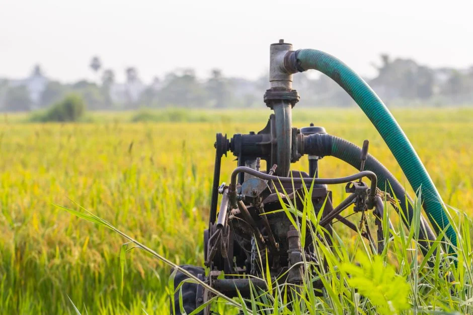
Reuse to cooling make-up is the lowest-CAPEX endpoint and the default on most Equinix IBX campuses in water-rich regions: RO permeate plus a corrosion-inhibitor dose feeds directly back into the cooling loop. Discharge to municipal sewer after pretreatment remains viable only where the local POTW accepts high-TDS effluent and the utility tariff is low—an option that is tightening under EU EED reporting as regulators ask for water-balance disclosure at the same granularity as energy. ZLD via MVR or brine evaporator is the only defensible path in water-stressed jurisdictions like Singapore or southern Spain, and it is the option aligned with Equinix's "water-positive" claims on certain sites. The trade-off is real, as MVR energy demand can offset PUE gains, a tension explicitly flagged by the npj Urban Sustainability 2025 paper (S2). Decision drivers boil down to four variables: local water-stress index, sewer discharge limits, energy cost in $/kWh, and ESG reporting obligations under CSRD and the SEC climate rule. For an engineering walk-through of how to size the evaporator side, see ZLD evaporator sizing for hyperscale concentrate.
Frequently Asked Questions
What wastewater streams does Equinix treat on-site at a data centre campus?
Equinix-style campuses treat two industrial streams on-site: cooling-tower blowdown (1,500–5,000 mg/L TDS) and RO reject from adiabatic or humidification systems (10,000–30,000 mg/L TDS). Sanitary sewage is normally handled by a packaged MBR or sent to the municipal sewer and does not pass through the industrial WW plant.
Does Equinix use zero liquid discharge for wastewater at any of its campuses?
Equinix reports water-positive outcomes on specific water-stressed campuses, which in practice requires either ZLD via mechanical vapour recompression or wind-aided enhanced evaporation of the RO concentrate. Sites in water-rich regions typically reuse RO permeate as cooling make-up and dispose of the concentrate off-site.
How is WUE calculated for a data centre, and what is a good target?
Water Use Effectiveness is annual site water consumption in litres divided by annual IT energy consumption in kWh (L/kWh). Hyperscale operators including Equinix target sub-1.0 L/kWh on water-efficient sites, with EU EED 2023/1791 now requiring annual disclosure of WUE and reuse KPIs for any data centre above 1 MW IT load.
What discharge limits apply to data centre cooling-tower blowdown?
Discharge limits are set by the local sewer or surface-water permit and typically cap TDS, heavy metals, and residual biocides; many EU municipalities now also require a water-mass-balance report under EED 2023/1791. High-TDS blowdown is increasingly rejected by POTWs, which is the regulatory pressure pushing campuses toward on-site RO reuse and ZLD.
Does on-site treatment reduce permitting risk for a hyperscale data centre?
Yes. On-site treatment that demonstrates reuse rates above the local baseline materially reduces permitting risk in water-stressed jurisdictions like Singapore, Dublin, and Amsterdam, all of which imposed construction moratoria between 2019 and 2022 over water and grid stress. Reuse performance is now reported alongside PUE under EU EED and CSRD, making the WW plant a permit-defining asset.