Why Iskandar Puteri Changes the Water Treatment Strategy
Iskandar Puteri’s reclaimed-water policy and rapidly growing data-centre cluster make water supply a project-design constraint, not a later sustainability exercise. SPAN published guidelines in September 2025 for data centres to use alternative water sources, according to The Edge Malaysia’s April 2026 report. The guidelines prioritise reclaimed water for cooling where available, with air-cooled, zero-discharge systems as another pathway.
The regional context supports a two-train treatment design. The Edge Malaysia reported in April 2026 that more than 17 data centres were in place in Iskandar Puteri, while residents had raised concerns about effects on local water supplies. In parallel, IWK and JSW entered a partnership supporting delivery of 12 MLD of treated sewage effluent through an integrated distribution system to water reclamation plants serving data-centre operators.
For each project, the engineering objective is to reduce freshwater withdrawal, control discharge and produce cooling make-up water with chemistry compatible with the selected cooling system. A blanket national requirement for reclaimed water is not the whole answer: source availability, delivery timing, approvals, cooling configuration and measured water chemistry still determine the feasible design. The broader data-center wastewater treatment guide explains how treatment should be aligned with site infrastructure and operating conditions.
Separate the Incoming Wastewater from the Cooling Loop
Incoming reclaimed water and cooling-tower blowdown must remain separate design streams because their contaminants, flow patterns and treatment objectives differ. Incoming reclaimed water is a variable municipal wastewater-derived supply that may contain suspended solids, organics, nutrients, pathogens, dissolved salts and treatment residuals. Cooling-tower blowdown is a purge from a recirculating loop; evaporation leaves dissolved solids behind, so the purge is more concentrated than the circulating water.
IDE identifies silica, calcium carbonate and calcium sulfate as key scale-forming constituents in cooling-tower blowdown. The Edge Malaysia reported in April 2026 that reclaimed water generally needs further filtration and chemical treatment to prevent corrosion and microbial growth in cooling systems. These are distinct barriers: pretreatment protects the incoming supply and downstream equipment, while blowdown recovery controls scale, concentration and discharge.
| Design stream | Source and behaviour | Principal treatment objective | Next destination |
|---|---|---|---|
| Incoming reclaimed water | Municipal wastewater-derived supply with variable solids, organics, nutrients, pathogens, salts and treatment residuals | Remove debris and suspended material; control organics, microbiology, pH and corrosion; protect downstream membrane and cooling equipment | Equalisation and storage, followed by site-specific pretreatment and polishing |
| Cooling-tower blowdown | Purge from a recirculating loop; dissolved constituents concentrate as water evaporates | Control scale-forming salts, conductivity and inhibitor concentration; recover water for cooling make-up where chemistry permits | Dedicated blowdown recovery train, then validated reuse or a defined discharge route |
| Combined site water balance | Incoming supply, evaporation, blowdown, production losses and storage changes | Minimise freshwater demand and discharge without compromising cooling reliability | Cooling make-up, permitted discharge and concentrate or sludge management |
This separation is also consistent with the cooling-blowdown treatment methodology: treat the source stream before combining it with another flow, then verify compatibility with its final use.
Characterize the Streams Before Selecting Equipment
Equipment selection should begin with a site water balance and complete analytical dataset, not a generic flow-per-megawatt assumption. For incoming reclaimed water, request daily and peak flow, pump pressure at the data-centre boundary and available storage volume. Record both raw and treated pH, conductivity, total dissolved solids, hardness, silica, alkalinity, chloride, sulfate, turbidity, suspended solids, biochemical oxygen demand, chemical oxygen demand, nutrients, residual chlorine and microbiological indicators.
For every cooling system, document evaporation rate, blowdown frequency, make-up-water source, cycles of concentration, inhibitor chemistry and current discharge route. Blowdown sampling should cover normal operation and maximum-concentration conditions, with conductivity, silica, calcium, hardness, alkalinity, sulfate, chloride, pH and temperature recorded for each condition.
Define the end use before specifying polishing. Cooling-tower make-up water has different requirements from a lower-temperature process loop or direct-cooling application. The final water specification should be derived from the cooling OEM, chemical-treatment programme, materials and operating conditions, then tested against membrane and equipment limits.
The Edge Malaysia reported in April 2026 that Computility Technology planned to use up to 4 MLD of reclaimed water at its Gelang Patah facility. That is a project-scale example, not a design flow for an Iskandar Puteri data centre. During supplier review, compare the proposed treatment components, valves and filter media against the measured design envelope rather than the reported project scale.
| Design input | Why it governs equipment selection | Information required |
|---|---|---|
| Hydraulic load | Determines tank, pump, filtration and membrane capacity | Average and peak incoming flow; blowdown flow; evaporation; storage buffer |
| Raw-water chemistry | Defines fouling, scaling and chemical-treatment risks | Complete ionic analysis, solids, organics, nutrients, microbiology and residual oxidant |
| Cooling concentration | Sets the maximum dissolved-solids concentration entering recovery | Cycles of concentration, inhibitor programme, maximum-concentration blowdown analysis |
| Reuse destination | Establishes the required permeate or treated-water quality | Cooling make-up, lower-temperature process or direct-cooling specification |
| Discharge and residuals | Controls concentrate volume and handling requirements | Permit conditions, receiving point, sludge handling route and electricity availability |
Build the Reclaimed-Water Pretreatment Train
A defensible reclaimed-water train removes inlet debris, separates suspended material, controls organics and microbiology, and protects sensitive downstream equipment from fouling and scale. Screening or equivalent inlet protection is required where the supply can contain rags, plastics or other debris. Dissolved air flotation can then address suspended solids, colloids, oil and grease where the measured load warrants it. The DAF treatment equipment should be selected against actual flow and loading rather than assumed wastewater conditions.
Multi-media filtration provides a further solids and turbidity barrier when the design must protect downstream reverse-osmosis membranes. UF pretreatment for reclaimed water can remove fine suspended solids, colloids and bacteria ahead of sensitive treatment; the supplied equipment description specifies 0.03-micron PVDF membranes, automatic backwash and air scour. These are equipment characteristics, not proof that every site requires UF or will achieve a particular feed-water condition.
Automatic chemical dosing should provide pH adjustment, coagulation and corrosion-control chemicals where required. The automatic chemical dosing system should integrate feed-rate control, tank-level management, alarms and containment appropriate to the hazardous chemicals selected.
Disinfection must follow a microbial-risk and residual-control assessment. UV provides an immediate physical disinfection barrier without relying on a persistent chemical residual, while chlorine dioxide has different dosing and control requirements; neither is interchangeable without evaluating downstream conditions. Reclaimed water requires further filtration and chemical treatment to prevent corrosion and microbial growth in cooling systems, as The Edge Malaysia reported in April 2026.
Final removal of scaling species and dissolved ions will generally require brackish-water reverse osmosis, but the supplied evidence does not establish a universal final-water specification for every Iskandar Puteri cooling system. The basis of design should be the confirmed cooling-water chemistry and equipment warranties.
| Process stage | Barrier addressed | Selection condition |
|---|---|---|
| Screening or equivalent inlet protection | Rags, plastics and debris | Present in the reclaimed-water supply |
| DAF | Suspended solids, colloids, oil and grease | Measured separation load requires high-rate removal |
| Multi-media filtration | Suspended solids and turbidity | Required for downstream membrane protection and verified SDI control |
| UF | Fine solids, colloids and bacteria | Feed chemistry and sensitivity justify membrane pretreatment |
| Chemical dosing | pH, coagulation, corrosion and residual control | Defined by mass balance, materials and treatment objectives |
| RO | Dissolved salts and scale-forming constituents | Permeate chemistry is required by the selected reuse destination |
Treat Cooling-Tower Blowdown for Safe Reuse
Blowdown recovery must be designed backwards from the required cooling-tower make-up-water chemistry. Establish permissible conductivity, hardness, alkalinity, silica and inhibitor concentration, then calculate whether the proposed permeate can satisfy them without exceeding the recovery of the cooling loop or destabilising treatment.
IDE reports that conventional brackish-water reverse osmosis typically plateaus at 75–80% recovery because scaling from silica, calcium carbonate and calcium sulfate becomes difficult to control. The supplied high-recovery alternative combines conservative local RO with controlled precipitation of sparingly soluble salts as dense solids and dynamic RO operation that alternates production with high-velocity flushing. The precipitation stage removes scale-forming constituents before the remaining brine is recycled.
An industrial RO system for cooling-blowdown recovery may form part of this train. The supplied product information states recovery rates up to 95%, but that is not a guaranteed site recovery. Actual performance depends on feed chemistry, pretreatment, scaling control, membrane selection and operating conditions. Membrane and filter selection should also be coordinated through the supplied RO and UF membrane and filter-element range.
Where high recovery cannot be justified, the design options are controlled precipitation with lower RO recovery, a lower-recovery system with a defined concentrate-management route, or a redesigned cooling configuration that reduces blowdown. These are engineering alternatives, not equivalent options: each shifts the balance between capital complexity, freshwater savings, concentrate volume and operating control.
IDE reported an industrial application operating at around 95% recovery with permeate silica reduced to about 1 mg/L. That result came from a site blending blowdown from 20 hybrid cooling towers, brine from an existing RO system and manufacturing wastewater; it is an application result, not a guarantee for an Iskandar Puteri data centre.
| Recovery option | Process basis | Main design risk | Required proof |
|---|---|---|---|
| Conventional brackish-water RO | RO with scaling control | Scaling and unstable recovery as concentrate concentration rises | Recovery calculation using worst-case blowdown chemistry and pilot or supplier process design |
| High-recovery RO with controlled precipitation | Conservative local RO, salt precipitation and dynamic membrane operation | Precipitation handling, hydraulic stability and solids removal | Complete mass balance, precipitation test and project-specific acceptance criteria |
| Lower recovery with concentrate management | RO or precipitation followed by defined residual handling | Concentrate disposal route and operating cost | Permit requirements, receiving capacity and lifecycle assessment |
| Cooling redesign | Reduce blowdown through operating or cooling-system changes | Thermal performance and capital implications | Integrated cooling-design evaluation and life-cycle comparison |
Match Each Treatment Objective to the Right Equipment
Treatment units should be compared by the barrier they remove, not by treating them as interchangeable packages. DAF separates floatable and suspended material; multi-media filtration reduces turbidity and particles; UF provides a finer membrane barrier; MBR combines biological treatment with membrane separation; industrial RO removes dissolved ions; chemical dosing controls pH and residual chemistry; disinfection addresses viable microorganisms; and sludge dewatering manages the solid residue produced upstream.
Where wastewater reuse requires biological treatment followed by membrane separation, the supplied MBR description identifies near-reuse-quality effluent below 1-micron filtration and a catalogue capacity of 10–2,000 m³/day. These are catalogue specifications, not a selected capacity for the site. Evaluate the integrated MBR treatment system only after the required biological load, flow profile and reuse quality are established.
A plate-and-frame filter press is justified only where upstream treatment generates sludge requiring dewatering. Its catalogue filtration areas range from 1–500 m², so the plate-and-frame sludge dewatering system must be selected from measured solids production, batch frequency and required cake handling rather than water throughput.
Disinfection equipment should be matched to the microbial-risk assessment. The UV disinfection system addresses microorganisms through UV exposure, while oxidant dosing requires separate consideration of residual control, chemical storage and downstream compatibility.
Total selection must account for recovery, concentrate volume, chemical consumption, energy use, footprint, maintainability and operator capability. For critical duty, ask suppliers to address membrane supply, spare pumps, dosing-system redundancy, instrument ranges, control integration, cleaning access and standby operation. A treatment train that cannot maintain cooling-water availability during a single component failure is not fit for the operating model.
| Equipment or process | Primary barrier | Do not use it to claim | Procurement check |
|---|---|---|---|
| DAF and multi-media filtration | Suspended solids, turbidity and floatables | Dissolved-salt removal | Measured hydraulic and solids loading |
| UF or MBR | Fine solids, colloids and microbiological separation | General dissolved-salt removal | Feed chemistry, membrane compatibility and cleaning strategy |
| Industrial RO | Dissolved ions and scale-forming species | Removal of untreated debris or organics without pretreatment | Recovery, permeate quality, energy and concentrate duty |
| Chemical dosing and disinfection | pH, corrosion, coagulation and microorganisms | A substitute for physical separation | Chemical demand, interlocks, containment and residual control |
| Sludge dewatering | Solid-residue volume and handling | Additional water reuse | Solids production, cake transport and disposal route |
Plan Commissioning, Monitoring and Community-Facing Performance
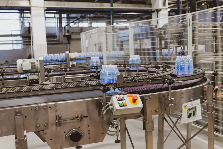
Commissioning should prove water quality, recovery, reliability and reuse under representative operating conditions. Specify online or frequent measurements for flow, pH, conductivity, turbidity, differential pressure, oxidant residual where applicable and cooling make-up-water chemistry. Include laboratory sampling for silica, hardness, alkalinity, sulfate, chloride, microbiology and other parameters required by the reuse specification.
Set project-specific acceptance tests for permeate quality, overall recovery, concentrate volume, automatic backwash, chemical dosing and standby-mode operation. The wastewater treatment requirements for a new data center provides a useful basis for converting the design intent into measurable acceptance criteria rather than vague performance claims.
Provide a bypass or contingency plan that protects cooling continuity during treatment upset, maintenance or interruption of the reclaimed-water supply. The plan should identify the permitted water source, maximum temporary blowdown, tank storage available, isolation points, operating authority and return-to-service checks. An operational bypass must not silently bypass reuse-quality or discharge requirements.
Track freshwater withdrawal, reclaimed-water use, cooling cycles of concentration, blowdown volume, treated-water production, energy, chemicals, sludge production and concentrate disposal. These operating records support water usage efficiency assessment and reveal whether the selected cooling configuration can sustain the assumed recovery.
The Edge Malaysia reported in April 2026 that Computility Technology expected 57% potable-water savings through rainwater harvesting and reclaimed water at its Johor project. This is a project-specific benchmark, not a universal Johor target. Public-facing reporting should distinguish source-water substitution, reduced potable-water withdrawal, recovered blowdown and discharge management so the site can report the actual water balance without implying that all measures are interchangeable. That reporting also responds to the community concerns about local water supplies reported by The Edge Malaysia in April 2026.
Frequently Asked Questions
Is reclaimed water mandatory for a data centre in Iskandar Puteri?
Not as a single blanket rule for every project. The Edge Malaysia reported in April 2026 that SPAN published guidelines in September 2025 prioritising reclaimed water for cooling where available, while also identifying air-cooled, zero-discharge systems as another pathway. The buyer should request written confirmation from SPAN, the relevant local authority, the reclaimed-water supplier and the discharge authority covering source availability, connection timing, permit conditions and the applicable cooling configuration for the specific site.
How should the treatment system be sized without a generic flow-per-megawatt estimate?
Size from measured and forecast flows, complete chemistry and the final reuse specification. The supplier should receive average and peak incoming flow, storage volume, evaporation, blowdown flow, cycles of concentration, raw and treated analyses, cooling make-up limits and concentrate-management constraints. Ask each bidder to show its design basis and identify any assumed value, because a generic per-megawatt flow cannot establish equipment capacity or recovery.
Why can cooling-blowdown recovery not be guaranteed from a regional rule of thumb?
Silica, calcium carbonate and calcium sulfate set the scaling constraints. IDE reports conventional brackish-water RO at typically 75–80% recovery and presents controlled precipitation plus dynamic RO as a higher-recovery alternative. A guarantee should therefore be conditional on worst-case blowdown chemistry, pretreatment, membrane selection, operating controls, concentrate handling and acceptance testing—not on the regional policy position alone.
What should a supplier quotation include so lifecycle cost and risk can be compared?
Require separate pricing for pretreatment, RO, pumping, electrical supply, chemicals, disinfection, membrane replacement, sludge or concentrate handling, monitoring, controls integration, commissioning and maintenance. Also ask the supplier to document scale-control measures, local service capability, membrane supply, controls compatibility, acceptance-test method and operator training. Without these items, capital-price differences can conceal higher chemical, energy, replacement and downtime costs.