
Why Textile Mills Are Specifying Cavitation Air Flotation
Textile dyeing and finishing effluent is one of the hardest industrial streams to clarify because the loadings swing batch-to-batch: residual reactive, disperse, and vat dyes; sizing agents and starches; non-ionic and anionic surfactants from scouring and washing; short fiber and lint; and pH/temperature swings between acidic dye baths and alkaline scouring washes. A flotation stage placed upstream of biological or membrane treatment has to absorb those swings without constant operator intervention.
Cavitation air flotation (CAF) has re-entered mill specifications in 2024–2026 because it does the same job as a conventional clarifier with fewer mechanical parts and a smaller footprint, and because reuse pressure keeps rising. The published textile reuse case study from Processes (S3, 2019-01) shows how far mills now go to recover water — a multi-stage train of flocculation–sedimentation, sand filtration, ozonation, ultrafiltration, and reverse osmosis — and that train only works if the upstream clarification is stable. For a textile ETP engineer, the question is therefore not whether to add flotation, but whether CAF is the right flotation technology, sized for the right influent, and integrated with the right downstream polishing step. Before any of that can be answered, the engineer needs the operating mechanism explained and the comparison against DAF drawn on textile-relevant terms.
Mills that already run a HydropureWater DAF system (4–300 m³/h) typically anchor their capacity benchmark there, and then evaluate CAF as a parallel option for new lines or for sites where the mechanical simplicity of two moving parts matters more than the saturator-based micro-bubble generation of a DAF. That comparison is the focus of the next two sections.
How a Cavitation Air Flotation System Actually Works
CAF generates micro-bubbles in a single submerged chamber, without a compressor, a pressure vessel, or a recycle stream. According to cnwwtp.com (S5), one or several CAF aerators are mounted in an aeration chamber inside a rectangular tank; the high-speed rotation of each aerator's impeller forms a local vacuum that pulls atmospheric air down into the water and shears it into millions of micro- and nano-bubbles. Those bubbles attach to suspended solids or to chemical flocculant particles already in the water, lifting them to the surface, where a mechanical skimmer sweeps the float into a scum trough. Purified water overflows into a clean-water chamber at the outlet end of the tank.
The mechanical consequence, drawn from the same source, is that the only moving parts inside the vessel are the aerator and the skimmer — there is no air compressor, no air-dissolving pump, and no saturation tank. Sigma DAF Clarifiers (S1) describes the same architecture in a slightly different vocabulary: air is drawn in from outside through specially designed aeration equipment and introduced into the aqueous medium, where it generates the bubbles that carry floatable particles upward while denser solids settle to the bottom of the same tank. Both floated scum and settled sludge are routed to a sludge container. Sigma DAF also notes that a portion of the clarified effluent is recirculated internally to keep wetted surfaces clean and to stabilize hydraulic conditions inside the unit. Because bubbles are produced in situ at atmospheric pressure, the contact zone operates without the pressurized recycle loop that defines a DAF — and that single design choice is what drives the smaller footprint and the lower installed power that mills cite when they switch.
CAF vs DAF for Textile Wastewater: A Direct Comparison
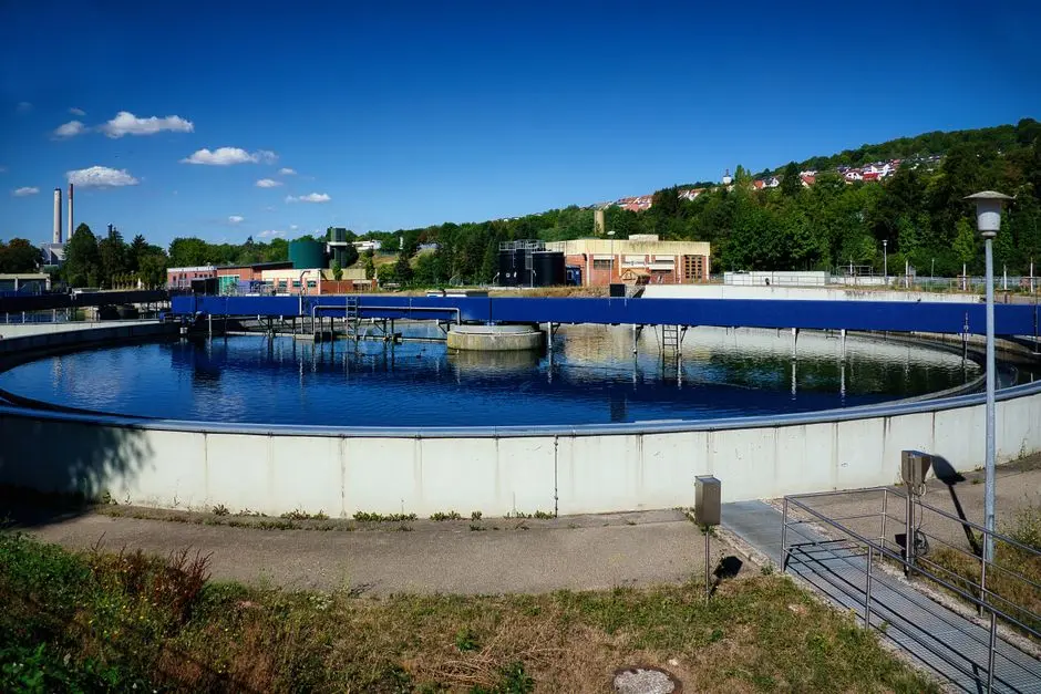
The procurement question every textile ETP engineer ends up asking is whether CAF or DAF is the better fit for the specific dyeing/finishing stream. The supplied sources do not give a head-to-head textile pilot study, so the comparison below uses only what the sources actually state: mechanism, claimed mechanical simplicity, capacity envelope, and the textile use cases each supplier publishes.
| Criterion | Cavitation Air Flotation (CAF) | Dissolved Air Flotation (DAF) |
|---|---|---|
| Bubble generation | Submerged high-speed impeller pulls in atmospheric air and shears it into micro/nano bubbles in the aeration chamber (S5) | Air is dissolved under pressure in a separate saturation vessel and released via a recycle stream into the contact zone (S6) |
| Major moving parts | Aerator and skimmer only (S5) | Aerator/saturator pump, compressor, and skimmer train (S1, S6) |
| External equipment | No air compressor, no air-dissolving pump, no saturation tank (S5) | Air compressor, saturation tank, recycle pump (S1, S6) |
| Footprint | Compact rectangular unit, few siting constraints (S1) | Compact rectangular unit; range covers 4–300 m³/h across 13 standard models (S6) |
| Sludge handling | Float and settled solids leave the same tank (S1); floated scum removed automatically with low moisture (S5) | Float removed by skimmer; settleable solids handled in the same or a downstream vessel (S1, S6) |
| Stated TSS removal | >90% claimed for general industrial duty (S5); no textile-specific figure in the supplied research | Not stated in the supplied HydropureWater catalog excerpt; textile-specific figure not provided |
| Named textile use case | "Color and impurities removal for textile dyeing wastewater" listed by cnwwtp (S5) | Textile listed as a proven sector in the HydropureWater DAF system range (S6) |
The honest reading of that table is that both technologies are marketed for textile duty, both run in compact rectangular tanks, and the deciding factors for a mill are mechanical simplicity (CAF's two moving parts vs. DAF's saturator train), the importance of the saturator-based micro-bubble generation for a particular dye/surfactant mix, and the layout constraints of the plant. Any textile-specific color, COD, or surfactant removal percentage is not given in the supplied research and must be confirmed with the bidder on the mill's own effluent — typically through a jar test or a short on-site pilot.
Sizing a CAF Unit for a Textile Effluent Stream
Sizing a CAF for a textile line is less about picking a model number and more about defining the influent envelope the unit will have to absorb. The capacity ladder is straightforward: Sigma DAF Clarifiers (S1) offers CAF units from 3 m³/h up to 250 m³/h, and the comparable HydropureWater DAF system (4–300 m³/h) is a useful benchmark when bidders quote capacity on a DAF basis. The supplier must then be given a complete influent data package before a model can be selected, because the hydraulic envelope alone does not capture the dye/surfactant load that drives coagulant demand and bubble-particle attachment.
| Parameter the mill must supply | Why it matters for CAF sizing |
|---|---|
| Peak and average hourly flow (m³/h) | Selects the hydraulic model within the 3–250 m³/h envelope (S1) and confirms surge headroom |
| Influent TSS (mg/L) | Drives float/sludge mass balance and skimmer speed; cnwwtp claims >90% TSS removal in general industrial duty (S5) — textile figure must be verified |
| Color (Pt-Co or absorbance at λ) | Defines coagulant/oxidant demand; textile-specific CAF removal is not stated in the supplied research and must be confirmed in pilot |
| COD / BOD (mg/L) | Sets whether CAF is enough on its own or whether biological treatment (see MBBR selection guide for biological treatment downstream of flotation) is still required |
| pH and temperature | Acid/alkali swing and hot wash liquors affect floc formation and the chemistry of bubble attachment |
| Surfactant class and load | Anionic/non-ionic surfactant from scouring drives foam and froth control on the skimmer |
| Fiber/lint content | Short fiber and lint load the skimmer and may dictate a pre-screen upstream of the CAF |
| Upstream coagulant/polymer choice and dose | CAF performance depends on coagulation/flocculation upstream — cnwwtp (S5) explicitly states bubbles attach to solids or chemical flocculants |
Placement also belongs inside the sizing question. Sigma DAF Clarifiers (S1) positions CAF as a pretreatment, as a post-biological secondary clarifier, or as a tertiary polishing step. For most textile mills the realistic placement is upstream of biology or membrane separation, with chemical conditioning handled by a HydropureWater automatic chemical dosing system so that coagulant and polymer feed are coupled to flow and to a setpoint the operator can adjust. A textile ETP design reference for 2026 is also worth reading alongside this sizing step, because the broader plant mass balance — equalization, cooling, neutralization, reuse targets — drives whether a 3 m³/h pilot skid or a 250 m³/h unit is the right starting point.
Designing the Sludge and Downstream Side of a Textile CAF
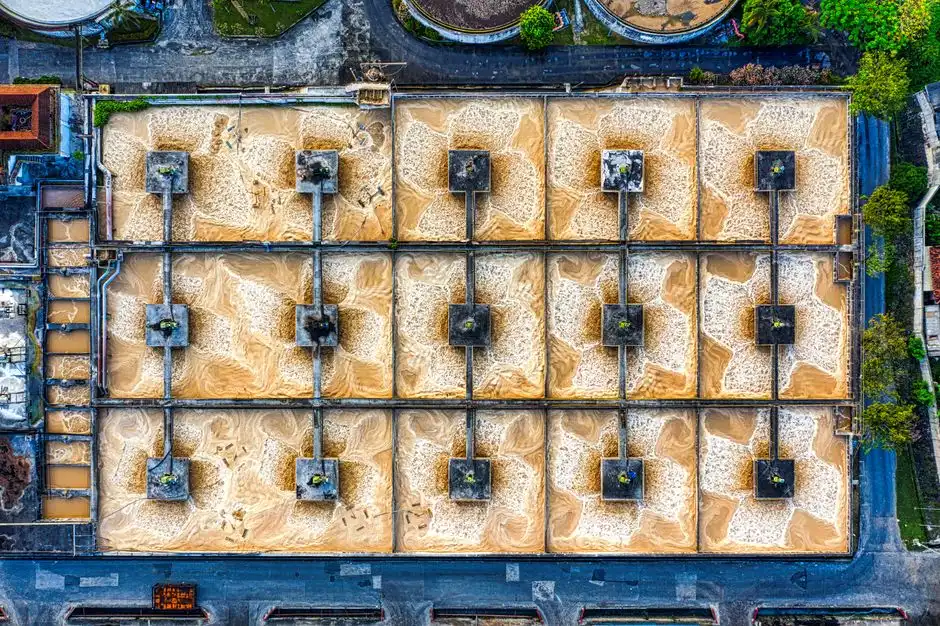
A common sizing mistake is to specify a clarifier without specifying what happens to the float and to the settled sludge. A CAF unit produces two sludge streams from a single tank, and both must be handled. Sigma DAF Clarifiers (S1) confirms this dual-stream layout: floated scum is swept to a surface trough while heavier settled solids are collected at the bottom of the same vessel, and both are routed to a sludge container. cnwwtp.com (S5) adds that the floated scum is removed automatically and continuously by the skimmer and that its moisture content is low, which reduces downstream disposal volume and cost.
The natural downstream pairing is mechanical dewatering. The HydropureWater plate and frame filter press for sludge dewatering covers filtration areas from 1 m² to 500 m², so a mill can scale the dewatering step to the float + settled sludge mass coming off the CAF without leaving the same vendor. Where reuse is the target, a pH/oxidation polishing step (ozonation, in the configuration described by Processes, S3) and a final membrane polish are typically added downstream of the CAF, with the lamella clarifier as a final solids catch before the membranes. Sludge handling should be checked against local disposal rules; a sludge disposal compliance guide is a sensible companion document when the float contains dye residues that affect disposal classification.
Selecting a CAF Supplier in 2026: What to Verify Before You Buy
The technical content above is necessary but not sufficient — a mill still has to choose a vendor. The 2026 shortlist should be filtered on five items that can be checked from public evidence, not on marketing claims.
- Mechanism match. Confirm the bidder's design actually generates micro-bubbles by cavitation at atmospheric pressure, with no compressor, no saturation tank, and no recycle pump, and that the unit has only two moving parts (aerator and skimmer) as described by cnwwtp.com (S5) and consistent with Sigma DAF (S1). If the bid includes a saturator vessel, the unit is a DAF, not a CAF, regardless of branding.
- Textile reference customers. Ask for named textile installations. Wuxi Gong Yuan (S4), for example, lists Qingmao Textile Corporation, Zhejiang Yinan Printing Corporation, and Jinyu Textile Corporation among its reference customers, which is direct evidence of textile-sector experience rather than a generic "industrial" claim.
- Standard model capacity ladder. Require the bidder to publish a model ladder that covers the mill's flow, comparable to the 3–250 m³/h envelope cited by Sigma DAF (S1) or to a documented range. Avoid bidders that only quote custom-engineered units with no standard platform.
- Full-scope supply. A CAF in isolation leaves interface gaps. Confirm the same vendor can deliver chemical dosing (HydropureWater automatic chemical dosing system), sludge dewatering (HydropureWater plate and frame filter press), and a downstream sedimentation or lamella clarifier (HydropureWater lamella clarifier). One-vendor scope reduces coordination risk on an ETP retrofit.
- Pilot or site trial data on textile effluent. The supplied research does not contain a textile-specific removal figure, so the only credible evidence base is the bidder's own jar-test or on-site trial on the mill's effluent. Reject any quotation that relies on a generic catalog removal number for a textile duty.
Frequently Asked Questions
What is a cavitation air flotation system and how does it work?
A cavitation air flotation system is a rectangular clarifier in which a submerged high-speed impeller pulls atmospheric air into the water and shears it into micro- and nano-bubbles inside a single aeration chamber, with no air compressor, saturation vessel, or recycle pump (S5). The bubbles attach to suspended solids or to chemical flocculant particles, lifting them to the surface where a skimmer sweeps the float off; heavier solids settle in the same tank and both streams are sent to a sludge container (S1). Part of the clarified water is recirculated internally to keep the wetted surfaces clean (S1).
Is cavitation air flotation better than DAF for textile wastewater?
Both technologies are marketed for textile duty — cnwwtp names "color and impurities removal for textile dyeing wastewater" as a CAF application (S5), and the HydropureWater DAF system range (4–300 m³/h) lists textile as a proven sector (S6). The deciding factors for a mill are mechanical simplicity (CAF's two moving parts vs. DAF's saturator train), the importance of saturator-based micro-bubble generation for a particular dye/surfactant mix, and the site footprint. Textile-specific color, COD, or surfactant removal percentages are not given in the supplied research and must be confirmed with the bidder on the mill's own effluent.
How do you size a CAF system for a textile dyeing plant?
Use the capacity ladder published by the bidder — Sigma DAF (S1) offers CAF units from 3 m³/h up to 250 m³/h — and submit a full influent data package: peak and average flow, pH and temperature, TSS, color (Pt-Co or absorbance), COD/BOD, surfactant class, fiber type, and the upstream coagulant/polymer program. CAF performance depends on the upstream coagulation/flocculation step (S5), so chemical conditioning is part of the sizing scope, not an add-on.
Should a CAF unit go before or after biological treatment in a textile ETP?
For most textile mills CAF is placed upstream of biological treatment or membrane separation to strip color, suspended solids, fiber, and surfactants before they reach the biology. Sigma DAF (S1) explicitly positions CAF as a pretreatment, as a post-biological secondary clarifier, or as a tertiary polishing step, so the placement is a design choice driven by the influent load and the reuse target rather than a fixed rule.
What is a realistic CAPEX range for an industrial CAF unit in 2026, and what should I ask a supplier?
The supplied research does not contain a price for a CAF unit, so any quoted number would be an assumption. Instead, send each shortlisted bidder a structured RFQ that includes: peak and average flow, influent TSS/color/COD/surfactant, the textile fiber and dyestuff class, the required effluent target, the placement in the train, and a request for textile-sector reference customers. Require the bidder to quote a standard model from their published capacity ladder, to include chemical dosing, sludge dewatering, and downstream polishing in the scope, and to provide pilot or site-trial removal data on a textile effluent. Comparing those responses side by side is a more defensible basis for a CAPEX decision than a generic price list.
Related Equipment
- HydropureWater DAF system (4–300 m³/h) — specifications, capacity range, and technical data
- HydropureWater automatic chemical dosing system — specifications, capacity range, and technical data
- HydropureWater plate and frame filter press — specifications, capacity range, and technical data
- HydropureWater lamella clarifier — specifications, capacity range, and technical data