Why MBBR? The Space-Saving Solution for High-Strength Industrial Wastewater
Industrial facilities often face a critical bottleneck: the need to increase wastewater treatment capacity within an existing, inflexible footprint. Consider a mid-sized food processing plant currently managing an influent COD (Chemical Oxygen Demand) of 500 mg/L. As production scales, the organic load surges, but the facility lacks the land required to build additional large-scale activated sludge basins. In such scenarios, conventional biological systems fail to meet strict discharge limits of ≤50 mg/L COD without massive capital investment in civil works. The Moving Bed Biofilm Reactor (MBBR) provides the technical solution to this dilemma by decoupling the Solid Retention Time (SRT) from the Hydraulic Retention Time (HRT).
MBBR systems reduce footprint by 60% compared to activated sludge, according to EPA 2023 retrofit case studies. This efficiency is achieved by utilizing high-surface-area carriers that allow for a significantly higher biomass concentration within the same reactor volume. Unlike Activated Sludge Processes (ASP), MBBR does not require a sludge return line (RAS), simplifying operations and eliminating the risk of filamentous bulking. This modular scalability makes it the preferred choice for high-strength streams in industries such as food and beverage, pharmaceuticals, pulp and paper, textiles, and landfill leachate management.
For engineers, the primary advantage lies in the system's resilience. Biofilms are inherently more robust than suspended growth flocs when facing toxic shocks or temperature fluctuations. By providing a stable habitat for specialized bacteria, MBBR ensures consistent effluent quality even under variable loading conditions. This makes it an ideal candidate for hospital wastewater treatment where space is at a premium and compliance is non-negotiable.
How MBBR Works: The Engineering Behind Biofilm Carriers and Microbial Action
The MBBR process is a biological treatment method where the biomass grows on small plastic elements that move freely in the wastewater. The engineering of an MBBR system is defined by the interaction between the carrier media, the aeration system, and the reactor hydraulics. The process typically follows these five engineering stages:
Step 1: Influent Entry and Mixing: Raw wastewater enters the aeration basin. Typical industrial basins range from 3–5 meters in depth with volumes scaled from 10 to 50 m³ depending on the organic load. In aerobic systems, the movement is provided by the aeration system; in anaerobic or anoxic systems, mechanical mixers are utilized to keep the carriers in suspension.
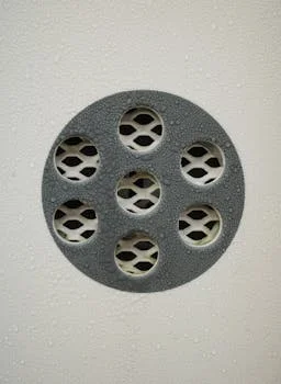
Step 2: Carrier Dynamics: The reactor is filled with biofilm carriers made of High-Density Polyethylene (HDPE) or Polypropylene (PP). These carriers have a density of approximately 0.95 g/cm³, allowing them to float and move easily with the water currents. Their design is critical; they must provide a high "protected surface area" where the biofilm can grow without being scrubbed off by carrier-to-carrier collisions.
Step 3: Biofilm Development: Microorganisms attach to the internal protected surfaces of the carriers. A mature biofilm typically reaches a thickness of 50–300 µm (per industry standards). This biofilm consists of multiple layers: an outer aerobic layer for carbon oxidation and nitrification, and an inner anoxic layer where denitrification can occur even in an aerated tank.
Step 4: Pollutant Diffusion: Pollutants such as COD, BOD, and ammonia diffuse from the bulk liquid into the biofilm. Here, the microbial population degrades the organic matter. Because the biomass is attached, the system can maintain a high SRT, which is essential for the growth of slow-growing nitrifying bacteria.
Step 5: Effluent Retention: Treated water exits the reactor through a retention screen. This screen—typically a wedge wire or perforated plate with a mesh size of 5–10 mm—prevents the carriers from leaving the basin while allowing treated water and excess "sloughed-off" biomass to pass through.
| Process Component | Engineering Function | Technical Specification |
|---|---|---|
| Aeration Basin | Biological degradation zone | 3–5m depth; Stainless or Carbon Steel |
| Biofilm Carriers | Microbial habitat | HDPE; 500–5,500 m²/m³ surface area |
| Aeration Grid | Oxygen transfer & mixing | Coarse or fine bubble diffusers |
| Retention Screen | Media containment | 5–10mm mesh; Stainless Steel 304/316 |
| Sloughing Mechanism | Biomass renewal | Natural hydraulic shearing |
MBBR Carrier Specifications: Surface Area, Material, and Loading Rates
The performance of an MBBR system is directly proportional to the available surface area of the carriers. Engineers must select carriers based on the specific organic loading rate (OLR) and the target effluent quality. High-performance carriers, such as the Eco Chip, provide a protected active surface area exceeding 5,500 m²/m³, which is significantly higher than traditional cylindrical media (typically 500–800 m²/m³).
When designing the reactor, the "fill ratio" is a critical parameter. This refers to the percentage of the bulk reactor volume occupied by the carriers in their dry state. Most systems operate at a 30–70% fill ratio. A higher fill ratio increases the total biomass available for treatment but also increases the energy required for mixing and aeration to ensure the carriers remain in a fluidized state.
| Parameter | Typical Value | Notes |
|---|---|---|
| Material | HDPE / PP / Composite | HDPE is preferred for chemical resistance (pH 2–12). |
| Shape | Cylindrical / Chip / Spherical | Chips offer higher surface area; cylinders are more robust. |
| Diameter | 10–25 mm | Ecologix Eco Chip utilizes 15 mm diameter. |
| Protected Surface Area | 500–5,500 m²/m³ | Higher surface area reduces required basin volume. |
| Fill Ratio | 30–70% | Optimized at 50% for most industrial applications. |
| Organic Loading Rate | 0.5–1.5 kg COD/m³/day | EPA 2024 benchmarks for industrial wastewater. |
| Hydraulic Retention Time | 4–12 hours | Varies based on influent strength and temperature. |
The organic loading rate (OLR) is another vital metric. For high-strength industrial streams, MBBR can handle OLRs up to 1.5 kg COD/m³/day. If the influent contains high levels of suspended solids or fats, it is recommended to learn how DAF systems remove 95%+ TSS and FOG before the water enters the MBBR stage to prevent carrier fouling.
MBBR vs. Alternatives: When to Choose MBBR Over Activated Sludge, MBR, or SBR
Selecting the right biological process requires a trade-off analysis between capital expenditure (CAPEX), operating expenditure (OPEX), and footprint. MBBR sits in a "sweet spot" for many industrial users who need high efficiency without the operational complexity or high cost of membrane systems.
| Parameter | MBBR | Activated Sludge | MBR | SBR |
|---|---|---|---|---|
| Footprint (m²/m³/day) | 0.2–0.5 | 0.8–1.5 | 0.1–0.3 | 0.6–1.2 |
| COD Removal | 90–97% | 85–95% | 95–99% | 85–95% |
| Sludge Production (kg/kg COD) | 0.2–0.4 | 0.4–0.6 | 0.1–0.3 | 0.3–0.5 |
| Energy (kWh/kg COD) | 0.8–1.2 | 1.0–1.5 | 1.5–2.5 | 0.9–1.3 |
| Capital Cost ($/m³/day) | 1,200–2,500 | 800–1,800 | 2,000–4,000 | 1,000–2,200 |
| Operating Cost ($/m³) | 0.10–0.25 | 0.15–0.30 | 0.20–0.40 | 0.12–0.28 |
| Ease of Retrofit | High | Low | Medium | Medium |
Decision Framework:
- Choose MBBR if: You have limited land, need to upgrade an existing plant (retrofit), or want a low-maintenance system that handles load fluctuations well.
- Choose Activated Sludge if: Land is abundant, and the primary goal is the lowest possible initial CAPEX for a large-scale municipal project.
- Choose MBR if: You require the highest possible effluent quality for direct water reuse or have extremely stringent discharge limits. Compare MBBR to MBR systems for high-efficiency wastewater treatment to see if the extra cost is justified for your facility.
- Choose SBR if: You have highly variable flow rates and require batch processing flexibility in a single tank.
MBBR Cost Breakdown: CAPEX, OPEX, and ROI for Industrial Applications
Justifying the transition to MBBR technology requires a clear understanding of the total cost of ownership. While the initial equipment cost (carriers and screens) may be higher than simple aeration equipment, the savings in civil engineering and sludge management often result in a superior ROI.
CAPEX Breakdown (per m³/day capacity): For a standard industrial MBBR system, the total CAPEX ranges from $1,200 to $2,500 per m³/day of capacity (2025 industry benchmarks). This is split between equipment costs ($800–$1,500)—which include the carriers, aeration grids, and retention screens—and civil works ($400–$1,000), covering the basin construction, piping, and electrical integration.
OPEX Breakdown (per m³ treated): The operating costs are dominated by energy consumption for aeration, which typically costs between $0.05 and $0.15 per m³. Carrier replacement, although minimal, should be budgeted at a 5–10% annual loss rate, adding $0.02–$0.05 per m³. Labor requirements are low, usually requiring only 0.5–1 full-time equivalent (FTE) for a 1,000 m³/day plant, contributing $0.03–$0.08 per m³. Total OPEX generally falls between $0.10 and $0.25 per m³ (per EPA 2024 cost reports).
ROI and Case Study: MBBR systems typically achieve a payback period of 3–5 years compared to conventional activated sludge. This is driven by 20–30% lower OPEX and significantly reduced sludge disposal costs. For example, a 500 m³/day food processing plant in Shandong reduced its OPEX by 25% and footprint by 50% by switching from activated sludge to a Zhongsheng Environmental MBBR system in 2024. The reduction in sludge volume alone saved the facility over $40,000 annually in hauling and tipping fees.
Common MBBR Challenges and How to Troubleshoot Them
While MBBR is a "set and forget" technology compared to MBR, it still requires proper operational oversight. Most issues stem from hydraulic imbalances or inadequate pretreatment.
Problem 1: Carrier Clumping or Floating This is often caused by over-aeration, which creates dead zones, or biofilm overgrowth (excessive thickness) that changes the carrier's buoyancy. Solution: Adjust the aeration rate to the target of 0.5–1.0 m³ air/m³ water/min. If the biofilm is too thick, increase the mixing intensity or temporarily reduce the organic load to allow for natural sloughing. Ensuring proper sludge management after MBBR with dewatering systems can also help maintain system balance.
Problem 2: Low COD Removal This usually occurs if the HRT is too short for the specific organic load or if the Dissolved Oxygen (DO) levels are insufficient. Solution: Increase the HRT to 8–12 hours for high-strength influent. Maintain DO levels above 2 mg/L. If the influent contains high concentrations of oils or solids, pre-treat high-TSS or oily wastewater with DAF before MBBR to ensure the biofilm remains active and accessible.
Problem 3: Excessive Sludge Production High Food-to-Microorganism (F/M) ratios or poor biofilm control can lead to rapid biomass growth and sloughing. Solution: Reduce the organic loading or increase the carrier fill ratio to provide more surface area for a more stable, thinner biofilm. Adding an anoxic zone can also help manage biomass and facilitate denitrification.
Problem 4: Carrier Loss Carriers escaping the reactor can damage downstream pumps and reduce treatment efficiency. This is typically caused by damaged retention screens or hydraulic surges. Solution: Inspect and maintain 5–10 mm stainless steel mesh screens regularly. Monitor flow rates to prevent surges and plan for a 5–10% annual carrier replenishment to account for natural wear and tear.
Frequently Asked Questions
Q: What is the typical lifespan of MBBR carriers?
A: MBBR carriers are designed for longevity, typically lasting 10–15 years under standard operating conditions (pH 6–9, temperature <40°C). An annual replacement rate of 5–10% is recommended to account for mechanical wear or minor losses through screens (per Ecologix 2024 data).
Q: Can MBBR treat high-ammonia wastewater?
A: Yes, MBBR is highly effective for nitrification, achieving 90–95% ammonia removal. For high-ammonia streams (>100 mg/L), it is necessary to increase the HRT to 12+ hours and potentially add an anoxic zone for a complete Nitrification-Denitrification cycle (cite EPA 2023 case studies).
Q: How does MBBR compare to MBR in terms of energy use?
A: MBBR is significantly more energy-efficient, using 30–50% less energy than MBR. This is because MBBR does not require high-pressure membrane scouring or permeate pumps. MBBR energy consumption is typically 0.8–1.2 kWh/kg COD, whereas MBR ranges from 1.5–2.5 kWh/kg COD.
Q: What are the discharge limits MBBR can achieve?
A: A well-designed MBBR system can consistently achieve effluent quality of COD ≤50 mg/L, BOD ≤10 mg/L, and TSS ≤30 mg/L. This meets most EPA and EU industrial discharge standards without the need for a secondary clarifier.
Q: Is MBBR suitable for small-scale applications?
A: Absolutely. MBBR's modular nature makes it ideal for small-scale plants. Explore compact MBBR-based sewage treatment for small-scale applications such as remote worker camps, hospitals, or small factories where a compact MBR system might be too complex to operate.