Why Coimbatore Changes the Treatment Train
A cooling tower in Coimbatore cannot be specified the same way as one in Frankfurt or Dublin. Tropical heat-load hours drive evaporative loss well above temperate-climate norms, so a tower that would run at cycles of concentration (COC) of 4 in a cool climate trends to COC 5–6 in Coimbatore to control makeup volume (Ecologix, S3). Higher COC concentrates every dissolved species in the recirculating loop, so total dissolved solids (TDS) lands at the upper end of the 1,200–6,000 mg/L range reported by Genesis Water Tech (S1) — typically the 4,000–6,000 mg/L band rather than the lower 1,200–2,000 mg/L end seen in soft-water U.S. sites. Groundwater and many municipal supplies in parts of Tamil Nadu carry hardness and silica that concentrate further, so the blowdown chemistry is scaling-prone from the start.
Consent is also site-specific. TNPCB consent to establish and consent to operate typically set limits on TDS, temperature rise, residual chlorine, and selected heavy metals at the discharge point, and the latest TNPCB general conditions for IT/ITES parks should be confirmed before the train is sized. The volume consequence is large: at COC 4 a tower loses roughly 25–30% of makeup water as blowdown (Genesis, S1), so a 20 MW site operating near the 1.8 L/kWh WUE benchmark (Ecologix, S3) generates millions of litres of blowdown per day — large enough that municipal sewer capacity, not treatment cost, often becomes the binding constraint.
What Is Actually in Cooling Tower Blowdown
Cooling tower blowdown (CTBD) is recirculating-loop water that has been purged to keep dissolved solids below scaling and corrosion thresholds. It is 4–8× more concentrated than the incoming makeup water, with TDS typically in the 1,200–6,000 mg/L band (Genesis, S1). The dominant scaling species are calcium, magnesium, alkalinity (HCO₃⁻) and silica — exactly the sparingly soluble salts that cap conventional brackish water reverse osmosis (BWRO) at 75–80% recovery (IDE Tech, S2).
Treatment chemicals accumulate proportionally with COC. A typical Coimbatore blowdown will carry residual biocides, scale inhibitors, dispersants, and corrosion inhibitors such as molybdate; older sites may also carry legacy chromate or high-phosphate chemistries (Genesis, S1; Ecologix, S3). Suspended solids sit in the 10–50 mg/L range despite basin filtration, with Cu and Zn leached from heat exchangers and planktonic bacteria plus biofilm fragments on top (Genesis, S1; Ecologix, S3). Effluent temperature is 30–40°C from the cooling loop (Ecologix, S3), which on top of TDS drives both TNPCB temperature-rise limits and biological fouling on downstream RO membranes.
Sizing Blowdown for a Coimbatore Hyperscale Site
The Ecologix benchmark is the most useful starting number. A 100 MW site at PUE 1.2 and WUE 1.8 L/kWh works out to 3,600,000 L/day of total water, of which roughly 60% is evaporative loss (Ecologix, S3). Blowdown follows B = E / (COC − 1), so at COC 5 the blowdown fraction of makeup is about 20% (Ecologix, S3).
Reported peak discharge flows for water-cooled data centers sit in the 6–19 L/s band, with up to 20 L/s reported for a medium-size facility at the hottest part of the load curve (LinkedIn / Arup, S4). A 20–50 MW Coimbatore hyperscale site should be designed at the upper end of that band, because the tropical wet-bulb profile and the decision to push COC toward 5–6 both raise the peak. Separately, the Climate Neutral Data Centre Pact 2025 caps new cool-climate potable-water data centers at WUE 0.4 L/kWh in water-stressed zones (LinkedIn / Arup, S4); although the pact is EU-led, hyperscale tenants increasingly apply it globally, so a Coimbatore consent application should be evaluated against that benchmark even though the site is warm-climate, not cool.
Unit Operations: From Pretreatment to Reuse or ZLD
Side-stream filtration is the first lever. A 10–25 μm self-cleaning spiral or multimedia filter is installed on 1–5% of the circulation flow, drops suspended solids to a level downstream membranes can accept, and lets the tower run higher COC (Genesis, S1). The capital band is USD 50,000–200,000 installed for typical data-center flow rates (Genesis, S1). A HydropureWater multi-media filter sized to the side-stream duty is a good fit at this stage, paired with a HydropureWater PLC-controlled chemical dosing skid for antiscalant and biocide feed.
Ultrafiltration (UF) is the standard RO pretreatment on CTBD. PVDF membranes at 0.01–0.1 μm operate at 10–30 psi, deliver 90–95% recovery, and need a chemical clean every 1–3 months (Genesis, S1). The HydropureWater UF system (0.03 μm PVDF, 2,000–40,000 L/h) with automatic backwash and air scour and turbidity tolerance to 300 ppm is specified for this duty. If particulates or metals need pulling out before the membranes, a HydropureWater lamella clarifier handles coagulation, flocculation and sediment removal in a small footprint.
Brackish reverse osmosis (BWRO) does the TDS cut. Operating at 150–400 psi with 95–99% salt rejection, permeate comes off at 10–50 mg/L TDS, suitable for direct return to the cooling tower or for blending with standard makeup to lift overall COC; recovery on CTBD is 50–85% (Genesis, S1). A 50,000 GPD RO unit on CTBD installs in the USD 250,000–500,000 band, with OPEX of USD 1.50–3.00 per 1,000 gallons covering energy, chemicals, membrane replacement and maintenance (Genesis, S1). The HydropureWater industrial RO (up to 95% recovery) sits in this envelope.
High-recovery RO is the route to choose when TNPCB limits push toward zero liquid discharge (ZLD). Conventional BWRO is capped at 75–80% recovery because silica, CaCO₃ and CaSO₄ reach scaling thresholds (IDE Tech, S2). A high-recovery system separates salt removal from osmotic pressure by precipitating the sparingly soluble salts in a fluidized bed reactor — scaling inhibitors are deactivated so silica, calcium carbonate and other problematic salts drop out as compact pellets onto seed material — and then runs RO in a dynamic cycling mode that alternates production with high-velocity flushing to keep the membrane surface inside the induction phase of crystallization. Operating at around 95% recovery with permeate silica down to about 1 mg/L (IDE Tech, S2), this is the architecture to specify when the site targets WUE closer to the Climate Neutral Data Centre Pact band.
Mechanical vapor compression (MVC) handles the RO concentrate tail when ZLD is required. MVC achieves 95–98% recovery on concentrate, distillate TDS below 10 mg/L, CAPEX USD 1–3 million for 10,000–30,000 GPD, and 15–25 kWh per 1,000 US gallons (Genesis, S1). Discharge polishing is a final cooling pond or cooling-tower pass to temper ΔT, then a polishing filter before the consented discharge point.
| Unit operation | Function | Key parameters | Indicative capacity (CTBD duty) |
|---|---|---|---|
| Side-stream filtration | Pre-filters circulating water; protects downstream membranes | 10–25 μm; 1–5% of circulation flow | Up to tens of m³/h |
| Lamella clarifier / DAF | Coagulation, flocculation, metals removal | Overflow rate per lamella design | Site-specific |
| UF (PVDF) | RO pretreatment, turbidity & bacteria cut | 0.01–0.1 μm; 10–30 psi; 90–95% recovery; CIP every 1–3 months | 2,000–40,000 L/h |
| BWRO | TDS, hardness, silica rejection | 95–99% rejection; permeate 10–50 mg/L TDS; 50–85% recovery | ~50,000 GPD reference unit |
| High-recovery RO (controlled precipitation + dynamic cycling) | Pushes recovery past 80% | ~95% recovery; permeate silica ~1 mg/L | Matched to CTBD peak |
| MVC brine concentrator | Concentrate volume reduction toward ZLD | 95–98% recovery; distillate TDS <10 mg/L; 15–25 kWh/k US gal | 10,000–30,000 GPD |
| Discharge polishing | ΔT tempering and final solids cut | Site-specific | Site-specific |
Reuse, Discharge or ZLD — Decision Framework for Coimbatore
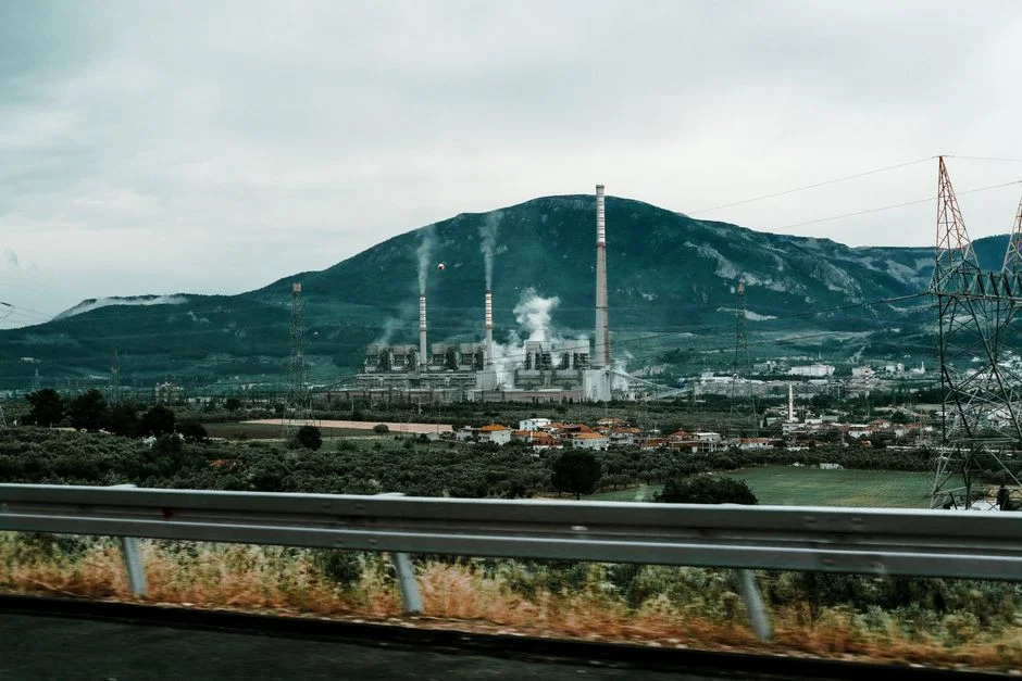
Three end-states cover the design space (Genesis, S1). Cooling-tower makeup reuse typically gives 60–85% recovery and the best economics because it cuts both freshwater intake and discharge fees. Discharge compliance is the fallback when reuse is not feasible; on-site treatment becomes mandatory when discharge TDS limits are tight, when a reuse mandate is in force, or when municipal sewer cannot accept the daily blowdown volume (Ecologix, S3) — Coimbatore hyperscale sites should plan for this case by default. U.S. discharge fees of USD 5–15 per 1,000 gallons (Genesis, S1) are a useful proxy for the direction of OPEX pressure; Indian municipal sewer tariffs are lower today but rising in water-stressed districts. Full ZLD is justified only when freshwater is scarce or discharge is prohibited, with CAPEX in the USD 3–8 million band and OPEX of USD 5–15 per 1,000 gallons at 95–99% water recovery (Genesis, S1).
| End-state | Trigger condition | Indicative recovery | Indicative CAPEX band (USD) |
|---|---|---|---|
| Cooling-tower makeup reuse | Default; limited sewer or reuse mandate | 60–85% | Site-specific |
| Discharge compliance | Tight TNPCB/CPCB limits; high TDS blowdown | Varies | Site-specific |
| Full ZLD | Discharge prohibited or freshwater scarce | 95–99% | 3–8 million (Genesis, S1) |
Capital and Operating Cost Bands for 2026 Planning
The published cost bands are budgetary only and are U.S.-sourced (Genesis, S1). For a Coimbatore site, an India-specific quote should be requested that includes civil works, TNPCB monitoring instrumentation, and 400 V / 11 kV power infrastructure assumptions.
| Item | CAPEX (USD) | OPEX (USD) | Source |
|---|---|---|---|
| Side-stream filtration | 50,000–200,000 | Low (solids disposal, maintenance) | Genesis, S1 |
| 50,000 GPD RO on CTBD | 250,000–500,000 | 1.50–3.00 per 1,000 gallons (energy, chemicals, membranes, maintenance) | Genesis, S1 |
| MVC brine concentrator (10,000–30,000 GPD) | 1–3 million | 15–25 kWh per 1,000 US gallons | Genesis, S1 |
| Full ZLD system | 3–8 million | 5–15 per 1,000 gallons | Genesis, S1 |
Frequently Asked Questions
What flow rate of blowdown does a 20 MW Coimbatore data center need to treat?
Using the Ecologix benchmark of 1.8 L/kWh at PUE 1.2, a 20 MW site uses about 720,000 L/day of total water, of which roughly 60% is evaporation. At COC 5, blowdown is on the order of 20% of makeup, so peak flows land in the 6–20 L/s band reported for medium data centers at peak cooling demand (Ecologix, S3; LinkedIn / Arup, S4). The upper end is the right design point for a Coimbatore hyperscale site.
Which HydropureWater unit operations cover the pretreatment → RO → polishing train?
The full train maps as: side-stream multi-media filter for 10–25 μm solids cut, lamella clarifier for coagulation and metals precipitation where feed requires it, PVDF UF (0.03 μm) as RO pretreatment, industrial brackish RO for TDS and silica rejection, PLC-controlled chemical dosing for antiscalant and biocide, and a chlorine dioxide generator paired with a UV sterilizer for biological control on the reuse loop. For a worked example of how these unit operations sit inside a hyperscale water cycle, the Manaus data center blowdown engineering guide covers a similar tropical, high-COC duty.
What is the 2026 CAPEX range for a blowdown reuse system in India?
Budgetary bands from Genesis Water Tech (S1) are: USD 50,000–200,000 for side-stream filtration, USD 250,000–500,000 for a 50,000 GPD RO on CTBD, USD 1–3 million for a 10,000–30,000 GPD MVC brine concentrator, and USD 3–8 million for a full ZLD system. These figures are U.S.-sourced and exclude civil works, TNPCB monitoring, Indian import duties, and 400 V / 11 kV power infrastructure — request an India-specific quote that itemises each of these before procurement signs off. For an India-relevant sizing reference, the containerized MBR STP sizing guide for India shows how the same budgetary discipline applies to a different Indian reuse duty.
What TNPCB/CPCB parameters govern blowdown discharge in Tamil Nadu?
TNPCB consent to establish and consent to operate for IT/ITES parks typically set site-specific limits on TDS, temperature rise (ΔT), residual chlorine, and selected heavy metals at the discharge point. Confirm the latest TNPCB general conditions for IT/ITES parks before sizing the train, and pre-build online monitoring for the parameters listed in the consent — Ecologix (S3) notes that effluent TDS above 2,000 ppm and ΔT above 5°C are typical triggers for mandatory on-site treatment rather than direct sewer discharge. For high-purity reuse applications, the RO pretreatment for high-purity water guide covers how the same parameter discipline carries through to UPW-style end-uses.
How long does a skid-mounted blowdown RO system take to ship and install?
Skid-mounted RO and UF skids typically have an 8–14 week fabrication window ex-works, plus 2–6 weeks for site installation and commissioning. India-specific lead time must be confirmed with the vendor, because containerised skids shipped from outside India add 4–8 weeks of ocean freight and customs, while India-fabricated skids compress to local fabrication lead times but introduce a separate quality-assurance hold point — request both lead time and a factory-acceptance-test plan in writing before placing the order.
Related Equipment
- HydropureWater industrial RO (up to 95% recovery) — specifications, capacity range, and technical data