Why Navi Mumbai Data Centers Need a Dedicated Blowdown Plan
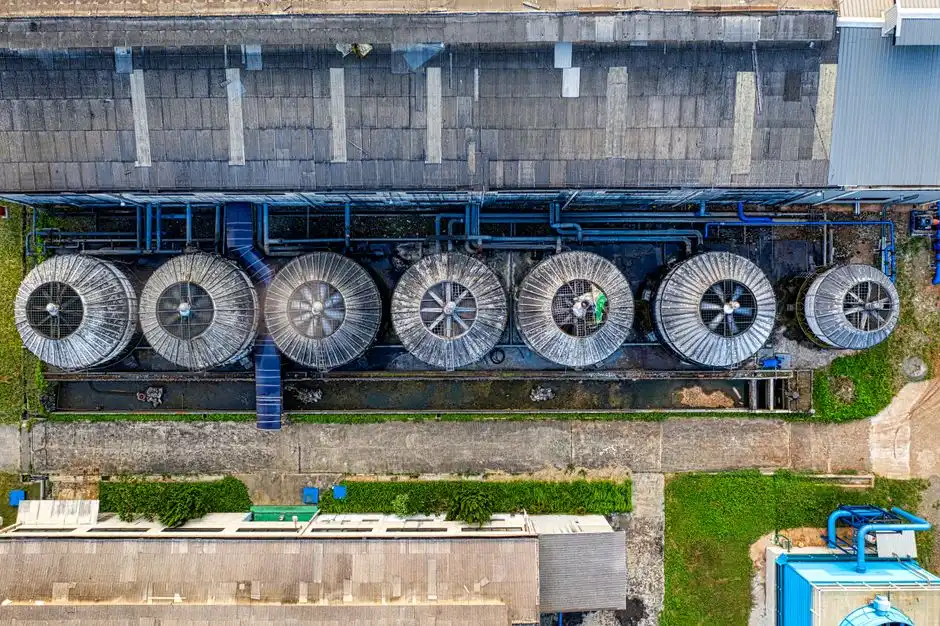
The NTT NAV1A campus in Navi Mumbai is 37,000 m², hosts 5,000 racks, and supports 30 MW of critical IT load, and it is the first Indian facility to deploy liquid immersion cooling and direct contact liquid cooling (DCLC) alongside traditional evaporative towers (S2). Despite that mixed cooling architecture, the broader industry is still water-heavy: 75–90% of data centers worldwide rely on water-based cooling as their primary method, and 20–30% of cooling water returns as liquid blowdown rather than evaporating (S5). For a 100 MW reference facility, daily water demand can reach 2 million liters, with roughly 60% lost to evaporation and the balance cycling through blowdown (S3, S4). On a Navi Mumbai campus, blowdown therefore remains a material stream that cannot be dismissed even where immersion and DCLC take a share of the heat-rejection load.
As hyperscale capacity expands across water-stressed Indian metros, three forces are tightening simultaneously: freshwater competition with municipal and agricultural users, TDS-based discharge caps, and rising scrutiny from the CPCB and state pollution control boards (S1, S3). On-site treatment is therefore shifting from a sustainability add-on to a license-to-operate requirement. A Navi Mumbai site typically has to handle three distinct wastewater streams: cooling-tower blowdown (CTBD), secondary-loop bleed from liquid immersion and DCLC systems, and sanitary plus equipment-wash water. The remainder of this article focuses on CTBD as the largest and most chemistry-constrained of the three, because it is the stream that drives membrane selection, antiscalant strategy, and any reuse-versus-ZLD decision.
Blowdown Quantity and Chemistry: What the Engineer Is Actually Fighting
At 4 cycles of concentration (COC), a data-center cooling tower typically loses 25–30% of its makeup water as blowdown; pushing to 5–6 COC shrinks that volume but concentrates every dissolved species downstream (S1, S4). Blowdown TDS runs 1,200–6,000 mg/L, which is 4–8× the makeup water, driven by source-water quality and the operator's COC target (S1). Mumbai and Navi Mumbai municipal makeup is high-TDS by global data-center standards, so for membrane sizing the engineer should default to the upper end of that 1,200–6,000 mg/L range until a site-specific water analysis is available (S1, S4).
The chemistry the engineer is fighting is brackish, silica-rich, and chemically dosed. Key contaminants include scaling minerals (calcium, magnesium, silica, alkalinity), treatment-chemical residuals (biocides, corrosion and scale inhibitors, dispersants), suspended solids in the 10–50 mg/L range from corrosion products, biofilm fragments, and airborne dust, and biological content such as planktonic bacteria and algae (S1). Some jurisdictions already enforce TDS discharge limits below 1,500 mg/L, which effectively prohibits untreated blowdown discharge and forces either reuse or further treatment (S1).
For sizing downstream equipment, a 50 MW heat load at 80% efficiency corresponds to evaporation of roughly 99,537 kg/h, and blowdown is then calculated as evaporation ÷ (COC − 1); a higher COC is the cheapest way to shrink downstream treatment capex (S4).
| Parameter | Typical Range / Value | Source |
|---|---|---|
| Blowdown fraction of makeup at COC = 4 | 25–30% | S1 |
| Blowdown TDS | 1,200–6,000 mg/L (4–8× makeup) | S1 |
| Suspended solids | 10–50 mg/L | S1 |
| Evaporation, 50 MW heat load at 80% efficiency | ~99,537 kg/h | S4 |
| Discharge-fee range in water-stressed regions | USD 5–15 per 1,000 gal | S1 |
| Tightening TDS discharge caps | < 1,500 mg/L in some jurisdictions | S1 |
Treatment Train from Filtration to Reverse Osmosis
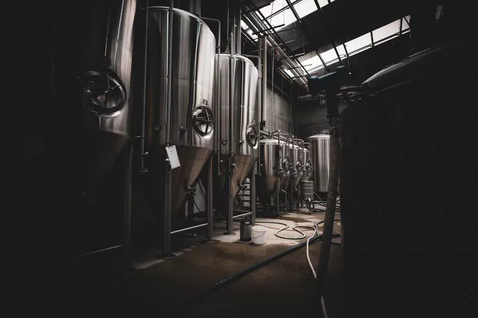
The standard high-recovery CTBD train pairs side-stream filtration with ultrafiltration ahead of an RO or NF membrane bank, with antiscalant and pH conditioning as mandatory pretreatment. Side-stream filtration is sized to 1–5% of total circulation flow, with self-cleaning spiral units rated to 10–25 µm that continuously remove suspended solids and biological load so the blowdown becomes membrane-friendly; capex is USD 50,000–200,000 for typical data-center installations (S1). When these units are paired with a multi-media filter as a polishing stage, downstream membrane fouling rates drop materially.
Ultrafiltration is the workhorse pretreatment for RO/NF. UF membranes at 0.01–0.1 µm pore size, operating at 10–30 psi, remove suspended solids, bacteria, viruses, and high-molecular-weight organics with 90–95% recovery, and they are also a defensible standalone option when only biological and particulate removal are required (S1). An ultrafiltration system in this role is backwashed with permeate and chemically cleaned every 1–3 months.
Reverse osmosis removes 95–99% of dissolved solids, hardness, silica, and most treatment chemicals, producing 10–50 mg/L TDS permeate suitable for direct cooling-tower makeup. Recovery on blowdown is 50–85%, limited by silica, calcium carbonate, and calcium sulfate scaling as concentrate TDS rises; an industrial RO system in this service requires operating pressures of 150–400 psi to overcome osmotic pressure, with feed filtered to < 10–15 µm and an automatic chemical dosing skid delivering antiscalant and pH adjustment (S1). For a 50,000 GPD blowdown RO train, installed cost is USD 250,000–500,000 with operating cost of USD 1.50–3.00 per 1,000 gallons treated (S1).
Nanofiltration at 75–150 psi and 70–85% recovery is the middle path when hardness and sulfate, not total TDS, drive the discharge or reuse limit, with permeate TDS at roughly 30–50% of feed (S1). High-silica makeup waters, which describe most of Navi Mumbai, favor RO for complete silica removal; NF can be a cost-effective first stage if hardness is the binding constraint (S1).
| Stage | Pore size / Pressure | Recovery | Permeate TDS / Function | Source |
|---|---|---|---|---|
| Side-stream filtration | 10–25 µm, self-cleaning | Continuous at 1–5% of circ. flow | Lowers SS and biological load | S1 |
| Ultrafiltration (UF) | 0.01–0.1 µm, 10–30 psi | 90–95% | SS, bacteria, virus, high-MW organics removal | S1 |
| Reverse Osmosis (RO) | 150–400 psi | 50–85% on blowdown | 10–50 mg/L TDS, cooling-tower makeup | S1 |
| Nanofiltration (NF) | 75–150 psi | 70–85% | 30–50% of feed TDS; hardness / sulfate selective | S1 |
Pushing Recovery Beyond Conventional Reverse Osmosis
Conventional brackish-water RO on CTBD plateaus at 75–80% recovery because silica, calcium carbonate, and calcium sulfate reach scaling thresholds beyond that point (S3). To move past that ceiling, two design philosophies are available. High-recovery architectures such as IDE's MAXH₂O intentionally deactivate scale inhibitors inside a fluidized-bed reactor, precipitating silica and calcium salts as dense pellets on seed material so the remaining brine is dominated by sodium chloride and can be looped to very high overall recovery; an industrial case study reports ~95% recovery with permeate silica at about 1 mg/L, achieved without multi-pass RO complexity (S3).
The thermal alternative is mechanical vapor compression (MVC), which reaches 95–98% recovery and produces distillate with TDS below 10 mg/L, leaving a 20–30% dissolved-solids brine for disposal. MVC capex is USD 1–3 million for systems processing 10,000–30,000 GPD, with energy consumption of 15–25 kWh per 1,000 US gallons of distillate (S1). Brine concentrators driven by waste heat from generators or chillers can lower MVC operating cost, but few data centers have enough recoverable waste heat without purpose-built heat supply (S1). Solar evaporation ponds offer a low-cost option for RO concentrate management in arid regions, but they depend on land area, evaporation rate, and rainfall and are not a typical Navi Mumbai fit (S1).
A combined RO + MVC train is the building block for partial or full ZLD: RO at 50–75% recovery followed by MVC on the RO concentrate at ~95% recovery delivers 85–95% overall system recovery with minimal liquid discharge (S1). Operators specifying this stage should plan membrane replacement and CIP cycles together, sourcing RO and UF membrane elements as a coordinated spares package rather than per train.
Decision Framework: Reuse, Discharge Compliance, or Zero Liquid Discharge
The choice between reuse, discharge compliance, and ZLD is set by local water economics and the permit envelope, not by equipment preference. Cooling-tower makeup reuse is the highest-value option, with 60–85% recovery that directly cuts freshwater intake and discharge volume (S1). Process-water reuse (irrigation, washdown) accepts lower recovery and lower spec, but depends on local reuse rules and downstream users (S1). Discharge compliance is justified mainly by avoided discharge fees, which in water-stressed regions now exceed USD 5–15 per 1,000 gallons; the economics matter most where TDS caps are below 1,500 mg/L (S1).
Full ZLD at 95–99% recovery combines RO, evaporative concentration, and a crystallizer producing solid salt cake. Capex is USD 3–8 million and opex USD 5–15 per 1,000 gallons, justified only where freshwater is unavailable or discharge is fully prohibited (S1). Partial ZLD that concentrates blowdown to reduce discharge volume by 80–90% captures most of the recovery benefit at a fraction of full ZLD cost, and pairs with deep-well injection, hauling, or special-permit discharge (S1).
On-site treatment becomes mandatory under three conditions documented in the research: when effluent exceeds municipal limits for TDS or temperature, when the site is in a water-scarce basin with reuse mandates, and when local municipal treatment cannot accept the daily blowdown volume (S4). All three conditions are increasingly plausible for Navi Mumbai hyperscale builds, and an on-site train must be designed against the worst-case of the three rather than the average.
| Strategy | Recovery | Capex (data-center scale) | Opex | Typical Justification | Source |
|---|---|---|---|---|---|
| Cooling-tower makeup reuse (RO/NF) | 60–85% | USD 250,000–500,000 for 50,000 GPD RO | USD 1.50–3.00 / 1,000 gal | Freshwater reduction, WUE target | S1 |
| Discharge compliance (RO + polishing) | 50–85% | USD 250,000–500,000 + polishing | USD 1.50–3.00 / 1,000 gal | Avoid fees in regions > USD 5–15 / 1,000 gal | S1 |
| Partial ZLD (RO + MVC, no crystallizer) | 85–95% | USD 1–3 M (MVC 10k–30k GPD) + RO | MVC 15–25 kWh / 1,000 gal distillate | Volume reduction 80–90% without full ZLD cost | S1 |
| Full ZLD (RO + MVC + crystallizer) | 95–99% | USD 3–8 M | USD 5–15 / 1,000 gal | No discharge permitted, no freshwater available | S1 |
Cost Economics, Compliance, and Frequently Asked Questions
Order-of-magnitude capex from the research: side-stream filtration USD 50,000–200,000; a 50,000 GPD blowdown RO system USD 250,000–500,000 installed; MVC USD 1–3 million for 10,000–30,000 GPD; full ZLD USD 3–8 million for data-center scale (S1). Opex benchmarks: RO USD 1.50–3.00 per 1,000 gallons treated; MVC 15–25 kWh per 1,000 gallons of distillate; ZLD USD 5–15 per 1,000 gallons (S1). Because these are US-market research ranges, a Navi Mumbai EPC should treat them as a sizing envelope, not a turnkey quote, and request INR-denominated vendor proposals for membranes, antiscalants, and energy. The baseline for a 30–100 MW Navi Mumbai campus in 2026 is a side-stream filtration + UF + RO train with partial ZLD or MVC considered site-by-site, with ROI weighted against Indian discharge fees and CPCB/SPCB consent conditions rather than US dollar benchmarks alone. For sanitary and equipment-wash streams, an MBR system is the standard polishing stage before reuse or discharge.
Frequently Asked Questions
What capex envelope should we budget for a blowdown treatment train on a 30–100 MW Navi Mumbai campus?
Using the US-market research ranges as a sizing envelope, a side-stream filtration skid sits at USD 50,000–200,000, a 50,000 GPD blowdown RO system runs USD 250,000–500,000 installed, MVC for 10,000–30,000 GPD is USD 1–3 million, and a full ZLD train is USD 3–8 million (S1). A Navi Mumbai EPC should request INR-denominated vendor proposals for membranes, antiscalants, and energy rather than relying on these dollar benchmarks as a turnkey quotation, and should size each stage against the upper end of the 1,200–6,000 mg/L blowdown TDS range until site-specific water analysis is available (S1, S4).
How do we choose between partial ZLD and discharge compliance for a hyperscale Indian site?
The decision should be driven by the CPCB/SPCB consent envelope and the local discharge-fee structure, not by equipment preference. Discharge compliance is justified where avoided fees exceed USD 5–15 per 1,000 gallons and TDS caps are below 1,500 mg/L; partial ZLD that concentrates blowdown to reduce discharge volume by 80–90% captures most of the recovery benefit at a fraction of full ZLD cost and pairs with deep-well injection, hauling, or special-permit discharge (S1). Confirm the consent conditions and the receiving WWTP's daily-volume capacity before locking the train, because the research shows on-site treatment becomes mandatory when municipal limits, water-scarcity mandates, or local WWTP capacity are binding constraints (S4).
What cycles of concentration should we target to minimize downstream treatment size?
Push COC from 4 toward 5–6 with chemical additives as the first line of defense, because blowdown volume drops in inverse proportion and downstream treatment capex falls with it (S4). Be aware that TDS, silica, calcium, and treatment-chemical residuals all concentrate proportionally, so 4–8× makeup values and the upper end of the 1,200–6,000 mg/L blowdown TDS range must be assumed for membrane sizing until site-specific water analysis is in hand (S1).
Can we skip membranes and use physicochemical treatment alone for blowdown?
Physicochemical trains (coagulation, flocculation, DAF, precipitation) are effective for rapid removal of particulates and metals, with 90–95% metal removal achievable in precipitation reactors, and they prevent overload on downstream RO (S4). However, they do not deliver the 95–99% dissolved-solids removal that RO provides, and they will not produce a permeate in the 10–50 mg/L TDS range needed for direct cooling-tower makeup (S1). For a hyperscale Navi Mumbai campus where reuse is the primary objective, physicochemical treatment is the necessary pretreatment stage, not a substitute for the membrane bank.