Why Surat, and why process wastewater is now a gating decision in 2026
Process wastewater in a Surat semiconductor fab or data hall is no longer a downstream environmental chore — it is now a permit-gating decision made at the front end of the project. A modern semiconductor fab can use up to 10 million gallons of water per day, with the majority tied up in wafer rinsing, CMP and UPW production; even a smaller OSAT line or a hyperscale data hall in Surat will move a comparable order of magnitude through chillers, humidification and regeneration loops, and most of that stream must be treated to reuse standard before it can be recycled. Surat sits on the Tapi–Ukai system, where industrial allocation is already constrained and where combined with the GPCB's tighter 2024–2026 consent reviews, water has moved from an OPEX line to a consent condition.
Locally, the engineering question splits into two camps. Semiconductor fabs in the Dholera–Sanand corridor generate the full chemistry — HF/BOE etch, HCl/H₂SO₄, NH₃, CMP slurry, photoresist solvents, scrubber blowdown and UPW reject. In-city Surat data halls and IT parks generate a different waste signature — DI/EDI regeneration blowdown, cooling-tower blowdown, chiller bleed, humidification bleed and RO reject — which is high in TDS, silica and hardness but low in metals and organics. Both arrive at the same Surat design office expecting a treatment train, and both leave with very different P&IDs. The rest of this article is built for that context: stream segregation first, high-recovery RO next, reuse or ZLD last, and GPCB and end-use limits designed in from the front end, not bolted on at commissioning.
The Surat wastewater stream matrix: fab and data-hall streams, side by side
Engineers should walk into a Surat kick-off meeting with a stream-by-stream map, not a generic process flow. HNS Watertech's framing is explicit: "the first question should be: What is actually in the wastewater, and which treatment stage is responsible for removing it?" — no single equipment model is the right starting point. The matrix below summarises the dominant streams a Surat project will see, the contaminant family that drives selection, and the first-stage unit operation that should follow.
| Stream | Source | Key contaminants | First-stage process |
|---|---|---|---|
| HF/BOE etch rinse | Wet etch, oxide strip | High F⁻, low pH, dissolved silica | Neutralisation + fluoride precipitation (calcium or alum) |
| HCl / H₂SO₄ acid waste | Clean, etch, post-CMP rinse | Low pH, high TDS, metals | Equalisation + pH correction + precipitation |
| NH₃-bearing waste | Litho coat/develop, RCA, scrubbers | Free and total NH₃-N, high pH swings | Equalisation + pH/temperature control; segregated from F⁻ line |
| CMP slurry wastewater | Polishing | Fine abrasive particles, metals, silica | Coagulation/flocculation + DAF or lamella clarifier |
| Photoresist stripper / solvent | Lithography, strip | Resins, NMP, TMAH, surfactants | AOP (UV/H₂O₂, ozone) + UF |
| Scrubber blowdown | Exhaust treatment | Acidic aerosols, metals, NH₄⁺ | Equalisation + neutralisation + precipitation |
| UPW reject / cooling-tower blowdown | UPW, HVAC | TDS, silica, hardness | Softening + RO; potential PFRO for high recovery |
| DI/EDI regeneration blowdown (data hall) | Polisher regeneration | Acid/caustic, high TDS | Neutralisation + RO recovery |
| Humidification / chiller bleed (data hall) | Cleanroom or precision cooling | TDS, silica, conductivity drift | Softening + side-stream RO |
| Sanitary / RO reject (data hall) | Domestic + polishing reject | Standard municipal pollutants + salts | Conventional biological + RO polishing |
Two practical rules from this matrix. First, keep HF/BOE lines separate from ammonia streams: combining them drives fouling and produces off-gas handling problems. Second, do not mix CMP slurry with photoresist solvent streams — IDE Tech's breakdown notes CMP alone can represent 30–40% of a fab's total wastewater volume, and forcing it through a biological or DAF stage shared with solvents destroys DAF performance and overloads downstream biology. For data halls, the converse applies: the dominant risks are silica scaling, hardness precipitation and RO recovery limits, not metal precipitation or AOP demand. Before any equipment is shortlisted, a baseline characterisation table covering flow, pH, TSS, fluoride, COD, NH₃-N, metals and conductivity is the prerequisite — IDE Tech and HNS Watertech both state explicitly that no generic recipe should be applied.
Core treatment train for Surat fabs: neutralise, float, oxidise, polish, recover
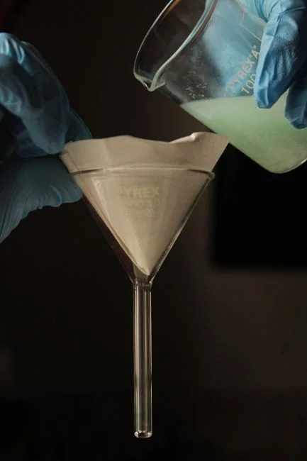
The unit operations on a Surat fab P&ID follow a fixed order, but the equipment inside each block is stream-specific. Equalisation and pH correction come first, and the IDE Tech writeup notes that production wastewater can vary significantly during the day, so equalisation "can help reduce sudden changes in flow, pH and contaminant concentration before downstream treatment." On a ramp-stage Surat fab this is mandatory — feed swings from a single tool dump can blow a downstream clarifier if the EQ tank is undersized. pH adjustment follows equalisation; IDE flags that acidic or alkaline streams may require controlled pH correction before precipitation, coagulation, biological treatment or any separation stage. Reagent selection here is a site-specific decision and is delivered through PLC-controlled chemical dosing skids sized to the actual jar-test programme, not a vendor default.
Coagulation, flocculation and dissolved air flotation are the workhorses for CMP solids and metal-bearing flocs. IDE and HNS both underline that DAF is not a default "because the wastewater is semiconductor" — it is a solids-separation step that needs the right hydraulic and chemical envelope. For footprint-constrained Surat sites, a lamella or high-rate settler is a credible alternative where surface-loading rates and chemistry allow. AOPs follow: IDE notes that "UV/H₂O₂, ozone, and advanced catalytic systems are commonly used" to degrade photoresist, solvents, surfactants and trace organics before any membrane — sizing logic for this block is covered separately in the 2026 AOP system design and sizing guide at AOP system design and sizing.
| Process block | Target | Surat-specific design note | Equipment link |
|---|---|---|---|
| Equalisation + pH correction | Flow, pH, load swings | Mandatory during ramp; sized for peak tool-dump events | — |
| Coagulation / flocculation | CMP and metal floc formation | Jar-tested per stream; not a generic dose | chemical dosing skids |
| DAF or lamella | Fine CMP particles, conditioned flocs | Selection depends on TSS, particle size, chemical programme | DAF units for CMP and metal-bearing streams |
| AOP (UV/H₂O₂, ozone, catalytic) | Photoresist, solvents, trace organics | Placed ahead of UF/RO to control fouling | — |
| UF + high-recovery RO + EDI | Polishing for reuse or UPW make-up | Silica-limited operation; pulse-flow RO proven at ~720 GPM | high-recovery industrial RO system |
The polishing block is UF → high-recovery RO → EDI where the design intent is reuse. HNS Watertech notes that "downstream treatment may therefore involve processes such as ultrafiltration, reverse osmosis, ion exchange or other advanced treatment technologies," and stresses that these "should not be selected as isolated pieces of equipment." The reference numbers for 2026 planning are the IDE benchmarks: state-of-the-art fabs recover 85–90% of their wastewater through high-recovery RO, advanced filtration and thermal polishing, and a single-stage PFRO retrofit on a ~720 GPM (~4,000 m³/day) line delivered 54% recovery on the new stage and 88% on the overall train — the unit operations listed above are exactly what made that 88% possible. For sludge generated across the train, a sludge dewatering press sized to the solids balance completes the line.
Data-hall trains are a different animal: regeneration, silica and cooling bleed
A Surat data-hall wastewater train should be designed as a polishing-led, low-chemistry system, not a fab-scale chemistry plant. The waste is low in organics and metals, but high in TDS, hardness, silica and regeneration salts — fundamentally the same constituents that determine the design of UPW rejects, EDI regeneration streams and cooling-tower blowdown inside a semiconductor plant. IDE Tech's UPW narrative makes the point: dissolved ions, silica and colloidal silica dominate the polishing challenge, and the standard stack is RO followed by EDI and UV.
The right unit operations for a Surat data hall are softening followed by RO for cooling-tower blowdown reuse, EDI/RO polishing for regeneration recovery, and dedicated neutralisation only for the small acid/caustic regeneration stream. Cooling-tower make-up, humidification make-up, toilet flushing and gardening are the realistic reuse envelopes — each has its own end-use limit and the train should be designed against the most constrained end-use, not against the discharge consent alone. Because the supplied research does not provide a Surat-specific 2026 reuse envelope, the practical move is to confirm the end-use list with the operator and GPCB before sizing, rather than copying a global benchmark. Equipment selection for these streams should draw on industrial softener skids for hardness and silica control, EDI polishing modules for regeneration recovery, and a high-recovery industrial RO system sized to the cooling-tower mass balance. The conceptual reference for fab-side reuse is the 2026 Pune semiconductor and data-hall engineering guide at the 2026 Pune semiconductor and data-hall engineering guide.
Recover, reuse or ZLD: the 2026 decision framework for Surat
The decision a Surat engineer must defend in front of a GPCB reviewer and a finance director is not "which membrane" but "where does the water stop." The 2026 working numbers are the IDE benchmarks: state-of-the-art fabs recover 85–90% of their wastewater, and a PFRO retrofit reached 54% recovery on the new stage and 88% on the overall train at ~720 GPM. These are planning values, not guarantees — IDE itself describes the PFRO case as an "18% increase over recovery levels before deployment," not a turnkey spec.
| Tier | Configuration | When it fits Surat 2026 | Trade-off |
|---|---|---|---|
| 1. High-recovery RO + reuse | UF → RO (single or two-pass) → EDI polishing; RO reject to GPCB-permitted discharge | Tapi allocation available, GPCB consent permits small brine discharge, no hazardous reject | Lower CAPEX; energy and antiscalant intensity rises with recovery |
| 2. Brine concentrator + reuse | RO + thermal/VC + reuse loop; reduced brine volume | Reject too saline for GPCB consent, no on-site ZLD | Higher thermal energy demand; CAPEX per m³/day rises |
| 3. Full ZLD with crystalliser | RO + brine concentrator + crystalliser; solids to authorised TSDF | Reject classified hazardous, no discharge path, or end-customer mandates ZLD | Highest CAPEX and thermal OPEX; compliance by construction |
The 2026 design moves listed by IDE — high-shear RO for challenging streams, slurry-resistant UF membranes, hybrid MLD/ZLD systems, advanced antiscalants tailored for semiconductor chemistries, and integrated wastewater segregation frameworks — are what make Tier 1 the realistic first choice for most Surat sites, with Tier 2 as a consent-driven escalation. Tier 3 is a permit-driven decision, not an efficiency-driven one. The IC wastewater ZLD and CAPEX benchmark guide at the 2026 IC wastewater ZLD and CAPEX benchmark guide covers the capital-cost framing in more detail. For Surat, the rule of thumb is: if GPCB will accept a small RO reject, stop at Tier 1; if the reject is too saline, escalate to Tier 2; if the reject is hazardous or no path exists, commit to Tier 3 with a crystalliser.
Surat compliance and CAPEX/OPEX framing for 2026
Surat projects are judged in two languages — GPCB/EPC compliance and capital budget — and neither tolerates assumptions. The compliance touchpoints that must be confirmed before design freeze are: GPCB consent under the Water Act (consent to establish and consent to operate), Environmental Clearance conditions for fab-scale projects, the Hazardous and Other Wastes (Management and Transboundary Movement) Rules for spent solvents and CMP sludge, groundwater-recharge restrictions in the Tapi basin, and the SWD/CEPT reuse envelope if discharge is to the municipal drain. The discharge standard itself is set by the consent conditions, not by a generic global limit — IDE Tech makes the same point for global permitting when it notes that "discharge is governed by local environmental authorities."
On cost, the design reality is that stream segregation forces multiple small units rather than one large ETP, which lifts CAPEX per m³/day but lowers long-term OPEX and consent risk — consistent with IDE's argument that "one size fits all" is the wrong starting point. OPEX is dominated by chemical cost, RO membrane replacement, energy for high-recovery pumps and (for ZLD) thermal energy, plus sludge disposal. Because the supplied research does not include a Surat-specific rupee benchmark, the practical move is to request itemised vendor quotes on a like-for-like basis (flow, recovery target, feedwater characterisation) rather than rely on a published per-m³ number. The forward-looking risk vector for any 2026 Surat design is PFAS: IDE states that PFAS are "chemically stable, resistant to conventional oxidation, and difficult to remove" and that the industry is under increasing pressure to eliminate PFAS discharges, which means the design should leave room for a PFAS removal stage — high-pressure membrane, activated carbon, ion exchange or AOP plus destruction — even if it is not the first thing tendered. A chlorine dioxide generator sized to the disinfection block and a sludge dewatering press sized to the solids balance are the standard finishing equipment on this train.
Frequently Asked Questions
How does a fab wastewater train differ from a data-hall wastewater train in Surat?
A fab train is chemistry-led: segregated acid, fluoride, ammonia, CMP and photoresist lines go through equalisation, pH correction, DAF or lamella, AOP and polishing, with the IDE reference case showing 54% recovery on a single PFRO stage and 88% on the overall train at ~720 GPM. A data-hall train is polishing-led: low organics, high TDS, silica and regeneration salts, so the right stack is softening plus RO plus EDI for cooling-tower, humidification and regeneration reuse, with neutralisation only on the small acid/caustic regeneration stream.
What does a semiconductor or data-hall wastewater plant actually cost in Surat?
The supplied research does not provide a published Surat CAPEX figure, and any number quoted without a site-specific flow, recovery target and feedwater characterisation should be treated as indicative only. The defensible move is to ask each shortlisted vendor for an itemised quote based on the same inputs: design flow (m³/day), target recovery (%), feedwater characterisation (TDS, F⁻, NH₃-N, COD, metals), end-use envelope, and discharge/consent constraints, then compare on a like-for-like basis. CAPEX per m³/day typically rises with stream segregation and ZLD, while OPEX is driven by chemical use, membrane replacement and energy.
How should a Surat EPC select a wastewater treatment supplier?
Selection should start with the stream matrix, not the machine model. HNS Watertech's published position is that the first question is "what is actually in the wastewater, and which treatment stage is responsible for removing it?" — a supplier who quotes a packaged ETP before seeing the characterisation is the wrong supplier. The check is: do they ask for and review baseline data (flow, pH, TSS, F⁻, NH₃-N, COD, metals, conductivity), do they run jar/pilot tests before sizing, and do they specify DAF, RO and EDI on actual feedwater envelopes rather than generic selection tables?
What recovery target should a 2026 Surat fab plan around?
Use 85–90% as the realistic 2026 planning floor for a state-of-the-art fab, based on IDE Tech's published benchmark for high-recovery RO with advanced filtration and thermal polishing, and 88% as the train-level reference from the PFRO case study. These are not commitments — actual recovery will be set by silica scaling, antiscalant selection and feed variability, and the design should be sized against the end-use envelope (cooling, UPW make-up, toilet flushing) rather than the headline recovery number.
What about PFAS in Surat semiconductor wastewater in 2026?
The supplied research flags PFAS as resistant to conventional oxidation and under increasing regulatory pressure, with the EPA confirming a PFAS roadmap and PFAS designated as hazardous substances under CERCLA. While the Surat-specific rule is not in the research, the safe design move is to leave space and budget for a PFAS removal stage — high-pressure membrane filtration, activated carbon, ion exchange resins, or AOP combined with destruction technologies — and confirm the local regulatory direction with GPCB before tender freeze.
Related Equipment
- PVDF ultrafiltration membranes — specifications, capacity range, and technical data