Why IC Wastewater Treatment Demands Specialized Equipment
Integrated circuit (IC) wastewater treatment equipment must process influent containing fluoride concentrations of 50–500 mg/L and copper levels of 10–100 mg/L, which far exceed the inhibitory thresholds of standard biological treatment systems. In typical industrial wastewater plants, fluoride levels exceeding 10 mg/L (IC50) cause severe enzymatic inhibition in activated sludge, leading to a total collapse of biological nutrient removal (BNR) processes. Consequently, semiconductor facilities require specialized multi-stage systems that combine chemical precipitation, membrane separation, and thermal evaporation to meet stringent global discharge standards, such as the Taiwan EPA limit for fluoride (<2 mg/L) and the EU Industrial Emissions Directive (IED) for copper (<0.1 mg/L).
A standard 300 mm wafer fab generating 200 gallons per minute (gpm) of wastewater faces a complex chemical profile that generic industrial systems are not engineered to handle. For instance, the high concentration of organic solvents used in photoresist stripping results in Chemical Oxygen Demand (COD) levels between 500 and 2,000 mg/L. Meeting a target of <100 mg/L COD for indirect discharge (per U.S. EPA guidelines) requires a robust secondary treatment stage, such as a Membrane Bioreactor (MBR), which provides the high biomass concentration necessary to degrade complex organic chains. Without IC-specific equipment, fabs risk non-compliance fines, permit revocation, and significant downtime due to system fouling from abrasive Chemical Mechanical Planarization (CMP) slurries.
| Parameter | Typical IC Influent | Taiwan EPA Limit | EU IED Standard | U.S. EPA (Indirect) |
|---|---|---|---|---|
| Fluoride (mg/L) | 50–500 | <2.0 | <15.0 | <5.0 |
| Copper (mg/L) | 10–100 | <1.0 | <0.1 | <0.5 |
| COD (mg/L) | 200–2,000 | <100 | <125 | <100 |
| TSS (mg/L) | 100–500 | <30 | <35 | <50 |
IC Wastewater Composition: Key Contaminants and Their Sources
The design of integrated circuit wastewater treatment equipment is dictated by the specific contaminants generated during the front-end-of-line (FEOL) and back-end-of-line (BEOL) manufacturing phases. Fluoride is primarily sourced from hydrofluoric acid (HF) used in wet etching and cleaning, often reaching peak concentrations of 500 mg/L in the acid waste stream. Copper contamination originates from the dual-damascene process, where electroplating and CMP steps release dissolved ions and fine metallic particulates into the effluent. According to detailed engineering specs for semiconductor wastewater systems, identifying these sources is critical for stream segregation, which prevents the dilution of toxic metals and optimizes treatment efficiency.
Organic loads, measured as COD, are highly variable and stem from photoresist stripping solvents like TMAH (Tetramethylammonium hydroxide) and NMP (N-Methyl-2-pyrrolidone). These compounds are often recalcitrant and require precise chemical dosing for fluoride precipitation in IC wastewater and subsequent biological oxidation. Additionally, CMP processes contribute significant Total Suspended Solids (TSS) in the form of fumed silica or alumina abrasives, which can be as small as 10–100 nm, requiring advanced coagulation and flocculation protocols before membrane filtration.
| Contaminant | Typical Range (mg/L) | Primary Process Source | Regulatory Benchmark |
|---|---|---|---|
| Fluoride | 300–500 | HF Etching / Wet Bench Cleaning | Taiwan EPA (<2 mg/L) |
| Copper | 50–100 | Electroplating / CMP Slurry | EU IED (<0.1 mg/L) |
| COD (Organics) | 500–2,000 | Photoresist Stripping / Solvents | U.S. EPA (<100 mg/L) |
| TSS | 100–300 | CMP Abrasives (Silica/Alumina) | Global Standard (<30 mg/L) |
| Antimony/Arsenic | 0.1–5.0 | Ion Implantation / Doping | Varies (<0.05 mg/L) |
Treatment Technologies for IC Wastewater: Performance, Costs, and Trade-offs
Selecting the appropriate technology for IC wastewater requires a balance between removal efficiency and the total cost of ownership, as high-purity requirements often necessitate multi-stage membrane or thermal systems. Chemical precipitation remains the industry standard for primary fluoride removal; by adding calcium chloride or lime, fluoride is precipitated as calcium fluoride (CaF2). While this method achieves approximately 95% removal, the theoretical solubility limit of CaF2 prevents it from reaching the <2 mg/L threshold without secondary polishing. For this reason, RO systems for fluoride and copper polishing in IC wastewater are frequently integrated to handle the remaining ionic load.
For organic removal, MBR systems for IC wastewater COD/TSS removal provide a compact footprint and high effluent quality, achieving up to 99% TSS removal and 95% COD reduction. However, MBRs do not remove dissolved fluoride or heavy metals, which must be addressed in the pretreatment or tertiary stages. In regions with strict "Zero Liquid Discharge" (ZLD) mandates, the integration of brine concentrators and crystallizers is necessary. While ZLD systems achieve 99.9% water recovery, they represent the highest CAPEX tier, often ranging from $20M to $50M for large-scale fabs, with significant energy demands of 10–15 kWh/m³ (Zhongsheng field data, 2025).
| Technology | Removal Efficiency | CAPEX ($/gpm) | OPEX ($/1k gal) | Key Limitation |
|---|---|---|---|---|
| Chemical Precipitation | F: 95% | Cu: 99% | $1,000–$2,000 | $1.50–$3.00 | High sludge volume |
| MBR (Biological) | COD: 95% | TSS: 99% | $1,500–$3,000 | $0.80–$1.50 | No fluoride removal |
| Reverse Osmosis (RO) | F: 98% | Cu: 95% | $2,500–$5,000 | $2.00–$4.00 | Membrane fouling |
| ZLD (Evaporation) | H2O Recovery: 99.9% | $10k–$25k | $15.00–$25.00 | High energy use |
Designing an IC Wastewater Treatment System: Step-by-Step Process Flow
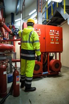
The engineering of an IC wastewater system begins with rigorous influent characterization, involving 24-hour composite sampling to account for the intermittent discharge patterns of batch processing tools. Because semiconductor fabs operate 24/7, redundancy is the most critical design parameter. A typical system utilizes a "N+1" philosophy for all critical pumps and dual-train configurations for membrane units to ensure that wastewater treatment never becomes a bottleneck for wafer production.
- Influent Characterization and Equalization: Measure fluoride, copper, COD, and pH. Equalization tanks must provide 2–4 hours of retention time to dampen pH swings and concentration spikes from tool cleaning cycles.
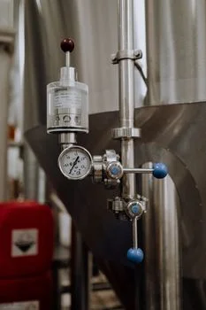
- Pretreatment and TSS Removal: Utilize DAF systems for TSS removal in IC wastewater pretreatment. DAF units operate at loading rates of 2–4 gpm/sq ft and are highly effective at removing the fine silica particles found in CMP slurry.
- Primary Chemical Treatment: Implement a two-stage chemical precipitation process. Stage one focuses on fluoride removal using calcium salts at pH 8.0–9.0. Stage two utilizes sulfide precipitation or specialized chelating agents to reduce copper to <0.1 mg/L.
- Secondary Biological Treatment: For fabs with high solvent loads, an MBR or IC (Internal Circulation) reactor is employed. MBRs typically operate with a Hydraulic Retention Time (HRT) of 6–12 hours, ensuring the complete breakdown of nitrogenous compounds like TMAH.
- Tertiary Polishing and Water Recovery: High-pressure RO membranes provide final polishing for fluoride and dissolved solids. In ZLD configurations, RO concentrate is sent to a Mechanical Vapor Recompression (MVR) evaporator to achieve total liquid-to-solid separation.
Redundancy measures should include emergency storage tanks sized for at least 24 hours of fab output to contain off-spec wastewater during system upsets, preventing environmental non-compliance and potential fab shutdowns.
CAPEX and OPEX Benchmarks for IC Wastewater Treatment Systems
Budgeting for integrated circuit wastewater treatment equipment requires an understanding of both the initial capital outlay and the long-term operational expenses driven by chemical consumption and energy. For a mid-sized 50 gpm fab, a hybrid system combining chemical precipitation and RO typically requires a CAPEX of $5M–$12M. In contrast, a full ZLD system for a 200 gpm facility can exceed $40M due to the inclusion of titanium-grade evaporators and crystallizers. According to cost benchmarks for chip fab wastewater equipment, engineering and permitting accounts for roughly 20–25% of the total project cost, particularly in highly regulated regions like the U.S. or EU.
OPEX is primarily driven by the cost of sludge disposal and chemical reagents. Lime or calcium chloride for fluoride removal is relatively inexpensive ($150–$250/ton), but the resulting hazardous sludge can cost $200–$500 per ton to transport and landfill. For fabs targeting high water reuse rates, the ROI of a ZLD system is often realized within 5–10 years, as it eliminates sewer surcharges ($0.50–$2.00/1,000 gal) and reduces the need for expensive ultrapure water (UPW) makeup, which can cost $3–$5 per cubic meter.
| System Configuration | Flow Rate (gpm) | CAPEX ($M) | OPEX ($/1k gal) | Payback (Years) |
|---|---|---|---|---|
| Chemical + MBR | 10–50 | $2.0–$6.0 | $1.20–$2.50 | 3–5 |
| Chemical + RO | 50–200 | $8.0–$20.0 | $2.50–$5.00 | 5–7 |
| Full ZLD System | 200+ | $25.0–$50.0 | $15.00–$30.00 | 7–10 |
How to Select the Right IC Wastewater Treatment System for Your Fab
The selection process for IC wastewater equipment must be data-driven, starting with a clear definition of the local compliance landscape. If the facility is located in a water-scarce region or a jurisdiction with a "Zero Discharge" mandate, a ZLD system is the only viable path despite the higher CAPEX. For fabs discharging to municipal sewers, a hybrid MBR and RO system often provides the best balance of compliance and cost. Engineers should also evaluate the RO design for metal removal in electroplating and IC wastewater to ensure the membranes are equipped with anti-fouling spacers and specialized antiscalants to handle the high mineral content of the waste stream.
Future-proofing is another essential criterion. Semiconductor fabs frequently upgrade their process nodes, which can change the wastewater chemistry (e.g., shifting from aluminum to copper interconnects). A modular system design allows for the addition of extra RO trains or chemical dosing skids without requiring a complete overhaul of the existing infrastructure. Finally, vendor selection should prioritize companies with documented experience in the semiconductor sector, as the ability to provide 24/7 technical support and rapid spare parts delivery is vital for maintaining the continuous operation required by modern IC manufacturing.
Frequently Asked Questions

What is the typical fluoride limit for IC wastewater discharge?
The Taiwan EPA sets one of the strictest global limits at <2 mg/L. Many U.S. fabs target <5 mg/L for indirect discharge to municipal treatment plants, while ZLD systems eliminate discharge entirely to meet zero-risk compliance standards.
How much does an IC wastewater treatment system cost for a 100 gpm fab?
A standard chemical precipitation and RO polishing system typically costs between $8M and $15M. If a Zero Liquid Discharge (ZLD) configuration is required, the cost increases to $25M–$40M depending on the complexity of the organic load.
Can MBR systems remove fluoride from IC wastewater?
No. MBR systems are designed for the removal of COD and TSS through biological oxidation and membrane filtration. Fluoride removal requires chemical precipitation (calcium-based) or high-rejection RO membranes.
What is the payback period for a ZLD system in a semiconductor fab?
The payback typically ranges from 5 to 10 years for fabs with flow rates above 200 gpm. This is driven by significant savings in water procurement costs and the avoidance of high sewer surcharges and environmental compliance penalties.
What are the key compliance standards for IC wastewater treatment?
Key standards include the Taiwan EPA (fluoride < 2 mg/L), EU IED (copper < 0.1 mg/L), and U.S. EPA (COD < 100 mg/L for indirect discharge). Local municipal permits may impose even stricter limits on specific metals like Antimony or Arsenic.