Why Helsinki Is a Different Design Problem
A Helsinki metropolitan data center in 2026 cannot be specified from a generic hyperscaler template because three forces collide on the same site: the Fortum–Microsoft Espoo–Kirkkonummi heat-recovery obligation, a cold-climate envelope that compresses evaporative cooling into roughly 1,200–1,800 hours per year, and a layered Nordic/EU permit stack that starts at the ELY-keskus and ends at HELCOM. Fortum committed an estimated €225 million between 2023 and 2027 to build heat-pump plants, pipeline connections, and district-heating upgrades that will lift the server-side 25–40 °C waste heat to a 60–90 °C district return, ultimately covering roughly 40% of district-heating demand in the Espoo–Kirkkonummi area for around 250,000 users (S4). Air-side economization covers an estimated 80–90% of annual hours in Espoo, so the cooling-tower evaporative load is concentrated in a narrow summer window, which shrinks blowdown volumes relative to a Phoenix or Dallas site. A 100 MW facility benchmarked against the 2 million L/day figure cited in industry reuse guidance drops to roughly 0.6–1.0 million L/day of make-up draw once economization absorbs most of the annual heat-rejection hours (per IDE, 2026; cross-checked against Fortum project data, 2024). The permit stack runs in parallel: an ELY Centre water permit under the Finnish Water Act (587/2011), an HSY (Helsinki Region Environmental Services) regional sewer agreement for any discharge into the Helsinki metropolitan network, and EU Industrial Emissions Directive (IED) 2010/75/EU notification once effluent exceeds 50 m³/day. A reader who treats Helsinki as a colder Quincy is going to oversize the treatment train and underdeliver on heat-recovery revenue.
The Helsinki Cooling Water Balance
Cooling-tower blowdown is fundamentally a salt-balance problem, and the cold-climate site changes the boundary conditions without changing the math. Per the Ketos industry analysis, 70–80% of water in evaporative cooling is lost as vapor and the remaining 20–30% leaves as liquid blowdown, with a closed-loop design able to cut net withdrawal to 5–10% of the equivalent once-through figure (per KETOS, 2026). Adapting the Mount Pleasant Phase 1 water balance of 234,000 gpd intake against 81,000 gpd discharge — scaling to 702,000/243,000 gpd at full build-out — to a Helsinki-equivalent facility, intake drops and blowdown drops proportionally because economization covers most of the year (per WPR, 2024; S2). At 4 cycles of concentration, the cooling tower multiplies incoming Ca/Mg by roughly four, so an Espoo make-up at 50–90 mg/L as CaCO₃ becomes 200–350 mg/L as CaCO₃ in the circulating water — the band the softener and reverse-osmosis (RO) train must be sized against. The salt mass leaving the cooling loop is therefore on the order of 200–350 mg/L × blowdown flow, and the salt mass that the treatment train must remove is the same quantity by conservation. The Fortum heat-pump lift also alters the cooling-tower inlet temperature: when server-side waste heat is pulled out at 25–40 °C and returned to the district loop at 60–90 °C (S4), the data-centre-side cooling loop must stay below roughly 40 °C, which lowers evaporative demand and tightens the blowdown mass-balance further. Engineers should run a source-water analysis with at least Ca, Mg, silica, chloride, sulfate, alkalinity, and conductivity before sizing the softener; typical Espoo potable TDS sits in the 80–150 mg/L range, but the limiting species is usually silica rather than hardness.
Discharge Rules: Baltic Sea, HSY Sewer, and EU IED
The regulatory floor for any Helsinki metropolitan data center starts at the EU Industrial Emissions Directive 2010/75/EU and the BREF on Common Waste Water and Waste Gas Treatment, which become binding once plant effluent crosses 50 m³/day — a threshold that any 50 MW+ hyperscaler build will clear on the first day of operation. The Finnish Water Act (587/2011) layers on top, with the Government Decree on Substance-Specific Discharge Limits (1022/2006) setting ceilings for TDS, chloride, sulfate, and temperature that the ELY-keskus translates into site-specific permit conditions; the typical chloride ceiling under an ELY permit is on the order of 500–700 mg/L for inland discharge and tighter near surface-water intakes. Helsinki coastal sites also sit under HELCOM Baltic Sea obligations on salinity, temperature, and nutrient discharge, which generally rules out direct sea outfall for a hyperscaler blowdown stream and pushes the design toward brine evaporation, crystallization, or zero-liquid-discharge (ZLD) ponding. HSY caps for the regional sewer system add a third layer, with practical TDS, nitrogen, and phosphorus limits that any blowdown sent to the HSY network must respect; in practice, hyperscaler projects in the HSY catchment pre-treat on-site to avoid paying the high-strength waste surcharge and to keep the discharge inside the HSY contract envelope. The combined effect is that a QWRU-style closed-loop reuse train (lime softening + ultrafiltration + RO) is the safest default, because it produces no industrial discharge to surface or ground water and concentrates all residuals into a manageable brine stream.
Treatment-Train Options for Helsinki Cooling Blowdown
Four design options cover the realistic design space for a 2026 Helsinki metropolitan build, and the choice is set by source-water TDS, ELY permit ceilings, and whether the site sits inside the Microsoft–Fortum heat-recovery envelope.
| Option | Core Process | Overall Water Recovery | Best-Fit Site | Discharge Path | Heat-Recovery Fit |
|---|---|---|---|---|---|
| A — Conventional HSY discharge | Multi-media filter + blowdown to sewer at 2–5 cycles | 0% reuse; full draw from municipal | <10 MW coastal site with confirmed HSY TDS headroom | HSY sewer under discharge agreement | Neutral; loop temperature unchanged |
| B — QWRU-style closed-loop reuse | MMF → lime softening → 0.03 µm PVDF UF → hot-process softening → 70–85% RO → permeate buffer (≥8 h) → cooling tower | 70–85% RO; near-closed-loop | Espoo/Kirkkonummi 50–150 MW, moderate-TDS source | Brine to lined pond or mechanical evaporator; no surface discharge | Strong — keeps loop ≤40 °C |
| C — High-recovery brine desalter | Conservative-recovery RO + fluidized-bed salt precipitation (e.g., IDE MAXH₂O-style) | ~95% overall; permeate silica ~1 mg/L | High-silica or high-TDS source water; tight ELY permit | Salt pellets hauled as solid waste; near-ZLD | Strong — ambient-driven membranes, no thermal lift |
| D — Zero-water closed-loop liquid-to-chip | Liquid-to-chip rack cooling; only humidification and sanitary discharge | No cooling blowdown | Temperate site with >85% economization hours and AI/HPC workload fit | Packaged MBR/MBBR for sanitary and humidification streams | Collapses heat source if applied campus-wide |
Options B and C are the reference designs for the Espoo–Kirkkonummi cluster because they keep the cooling loop at the low end of the 25–40 °C server-side window (S4), so Fortum's heat pumps still have warm source water to lift. Option A is acceptable only at sub-10 MW sites where HSY TDS headroom is confirmed in writing. Option D is the most water-efficient but eliminates the Fortum heat-recovery revenue stream if applied to the whole campus; the standard compromise is a hybrid — liquid-to-chip for AI/HPC halls, hybrid evaporative-plus-liquid-to-chip for the legacy whitespace, sized so the cooling-tower load still feeds the Fortum return loop. The other regional guides on this site — for example the Quito data center blowdown treatment guide and the Alexandria data center blowdown treatment guide — use the same four-option matrix; Helsinki collapses the choice toward B or C because of the heat-recovery obligation.
Equipment List for the QWRU-Style Train in a Nordic Climate
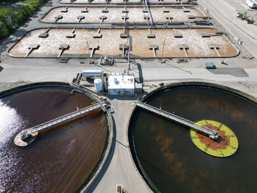
The QWRU equipment list carries over to a Nordic climate with two adjustments: a hot-process softener (HES) is required because influent temperature drops below 10 °C in winter and cold lime alone will not hit residual hardness targets, and all outdoor skids need enclosure heat-tracing to survive −20 °C ambients. The pretreatment train starts with a multi-media filter sized to drop turbidity below 1 NTU ahead of the 0.03 µm PVDF ultrafiltration system, which in turn feeds an industrial RO system running at 70–85% recovery to hit a 300–350 µS/cm permeate band, blended online through the day to hold conductivity on setpoint. A lime-dosing skid (calcium hydroxide for Ca/Mg hardness) followed by hot-process softening, with a PLC-controlled chemical dosing skid to hold Ca/Mg removal on setpoint across flow variation, sits between the multi-media filter and the UF (S2). Bacterial control on the make-up stream uses a chlorine dioxide generator or a UV sterilizer — either is acceptable under the Microsoft chemistry stance (S2). Sludge from the softening stage is dewatered with a plate-and-frame filter press, and the RO concentrate goes to a lined brine pond sized for the Helsinki evaporation rate, with a mechanical evaporator as the redundancy path during the low-evaporation winter months. Solids are hauled off-site on a 2–3 year cycle, matching the Quincy operating cadence (per EPA case study, 2021; S2).
| Unit Operation | Design Function | Typical Helsinki Sizing Band | Notes for Nordic Climate |
|---|---|---|---|
| Multi-media filter (MMF) | TSS / turbidity reduction upstream of softening | 10–25 m³/h per vessel, dual-vessel | Inside heated enclosure; automatic backwash on differential pressure |
| Lime softening reactor + clarifier | Ca(OH)₂ dose for Ca/Mg hardness; sludge to filter press | 10–20 m³/h per train | Lime slaker in heated room; pH probe on PLC |
| Hot-process softener (HES) | Post-lime polish to low residual hardness before UF | 10–20 m³/h | Required because cold lime underperforms below 10 °C |
| 0.03 µm PVDF UF | Particulate and microbial barrier before RO | 2,000–40,000 L/h per skid | Air-scour + backwash; CIP loop heat-traced |
| Industrial RO | 70–85% recovery to 300–350 µS/cm permeate | 5–15 m³/h permeate per train | Energy-recovery device on concentrate; VFD on HPP |
| Permeate buffer tank | ≥8 hours of permeate storage | 40–120 m³ | Indoor; level + conductivity instrumentation |
| ClO₂ generator / UV sterilizer | Bacterial control on make-up | 0.5–2 kg/h ClO₂ or 5–20 m³/h UV | Either is acceptable; UV is chemical-free |
| Plate-and-frame filter press | Dewater softening sludge to ~30–35% dry solids | 5–15 m³/h feed | Cake to lined disposal; filtrate returned to headworks |
| Lined brine pond or mechanical evaporator | RO concentrate management | 500–2,000 m³ pond, with evaporator redundancy | Geomembrane HDPE liner; leak detection |
| PLC-controlled chemical dosing skid | Coagulant, antiscalant, pH adjustment | Per train | Integrated with SCADA; peristaltic or diaphragm pumps |
Integrating the Train with the Fortum Heat-Recovery Loop
The Fortum heat-recovery contract is the variable that no generic hyperscaler template captures, and it changes the optimum treatment train in two specific ways. First, Fortum's heat pumps lift server-side 25–40 °C waste heat to 60–90 °C for the district return loop (S4), which means the data-centre-side cooling loop must stay below roughly 40 °C — a constraint that fits a standard RO permeate cooling loop but rules out thermal brine concentrators or mechanical vapor compression (MVC) that would dump additional heat into the brine side and overheat the loop. Second, the 250,000-user heat load (S4) is the anchor revenue stream for the entire Espoo–Kirkkonummi project, so the wastewater treatment train must be reliable enough that an outage does not force a server shutdown and therefore a heat-supply miss; a redundant UF/RO train, an evaporator on the brine line, and a permeate buffer tank sized for at least 8 hours (matching the QWRU 8-hour buffer per the EPA case study, 2021) are no longer optional. The implication is that the train should reject heat to ambient (cooling-tower side) rather than to the brine side, which favors ambient-driven membrane systems over thermal processes. On the metering side, Fortum needs to verify heat volumes and temperatures while the operator verifies permeate flow and conductivity; both data sets must land on the same SCADA, and a SCADA retrofit for wastewater plants is the natural follow-up read for any operator consolidating legacy hardware into a Fortum-facing telemetry stack.
Decision Framework: Which Train for Which Helsinki Site

Use this matrix to pick a train before you start equipment selection. The four variables that drive the answer are site size, source-water TDS, the ELY permit envelope, and whether the site is inside the Fortum heat-recovery catchment.
| Site Profile | Source-Water TDS | ELY Permit Pressure | Fortum Heat-Recovery Contract? | Recommended Train | Key Equipment Emphasis |
|---|---|---|---|---|---|
| Coastal <10 MW, no hyperscaler water-positive commitment | Low–moderate | Standard | No | Option A — HSY discharge | MMF + blowdown; confirm HSY TDS headroom in writing |
| Espoo/Kirkkonummi 50–150 MW, moderate source TDS | Moderate | Standard | Yes | Option B — QWRU-style closed-loop | Lime + UF + RO; ≥8 h permeate buffer; evaporator redundancy on brine |
| Inland site, high-TDS source or tight ELY chloride cap | High, or silica >30 mg/L | Tight | Optional | Option C — Brine desalter (~95% recovery) | Conservative RO + fluidized-bed precipitation; salt pellet handling |
| Hamina-style cold-climate site, >85% economization, AI/HPC fit | Any | Standard | Yes (e.g., Haminan Energia) | Option D — Zero-water liquid-to-chip with hybrid fallback | Liquid-to-chip rack manifolds; packaged MBR for sanitary + humidification |
For a procurement engineer, the practical sequence is: (1) confirm the source-water analysis with at least Ca, Mg, silica, chloride, sulfate, and conductivity; (2) confirm in writing whether the site is inside the Fortum catchment and what heat-recovery temperature window applies; (3) request an indicative ELY permit envelope from the local ELY-keskus before locking the train; (4) shortlist Option B for the default Espoo–Kirkkonummi case, Option C if silica is the limiting species, and Option D only when the workload mix is genuinely AI/HPC-dominant and the heat-recovery contract allows for the lower source temperature. The Guayaquil data center blowdown treatment guide covers the tropical and water-stressed counterpart; the same Option B/C/D logic applies, with the climatic and permit variables flipped.
Frequently Asked Questions
What permits does a data center need to discharge cooling blowdown in Helsinki?
An ELY Centre water permit under the Finnish Water Act (587/2011) is the primary instrument, with site-specific TDS, chloride, sulfate, and temperature ceilings set by the Government Decree on Substance-Specific Discharge Limits (1022/2006). A separate HSY sewer discharge agreement is required for any blowdown sent to the Helsinki metropolitan sewer network, and EU Industrial Emissions Directive 2010/75/EU notification applies once plant effluent crosses 50 m³/day.
Can a Helsinki data center reuse all of its cooling blowdown?
Yes. A QWRU-style train (lime softening + 0.03 µm PVDF UF + RO) routinely hits 70–85% RO recovery, and a high-recovery brine desalter can push overall recovery to roughly 95% with permeate silica around 1 mg/L (per IDE, 2026). The QWRU reference design blends online to a 300–350 µS/cm permeate band and returns essentially all flow to the cooling tower, with brine to lined ponds and solids hauled every 2–3 years (per EPA case study, 2021).
How does the Fortum heat-recovery contract change the wastewater treatment design?
It caps the cooling-loop temperature at roughly 40 °C because Fortum's heat pumps lift 25–40 °C server-side heat to a 60–90 °C district return (S4). This rules out thermal brine concentrators and mechanical vapor compression, and favors ambient-driven membrane trains. It also raises the cost of a treatment outage, because a treatment trip can force a server shutdown that simultaneously cuts the district-heating supply to the 250,000-user catchment.
Is liquid-to-chip cooling viable in Finland's climate?
Yes. The Microsoft Mount Pleasant blueprint shows it works in cold-climate temperate regions with significant economization hours (per WPR, 2024), and the Google Hamina project demonstrates waste-heat recovery from liquid-cooled servers into the Haminan Energia district-heating network — planned to supply 80% of the town's annual district-heating demand from late 2025 (S4). Espoo and Kirkkonummi sit in the same climatic envelope and are technically compatible with the same archetype.
What is the typical blowdown volume for a 50 MW Helsinki data center?
Roughly 0.3–0.5 million L/day at 4 cycles of concentration, versus 1.0 million L/day for an equivalent 100 MW evaporative-cooled facility in a warmer climate (per Ketos, 2026; cross-checked against the 2 million L/day per 100 MW benchmark from IDE, 2026). Cold-climate economization is the dominant reason the Helsinki number is lower per megawatt than the global benchmark.