What Makes Enzyme Manufacturing Wastewater Hard to Treat
Enzyme manufacturing wastewater is not a generic food-and-beverage effluent — it is the combined bleed from three unit operations, each with a different character. Fermentation broth carries 10,000–40,000 mg/L COD and 5,000–20,000 mg/L BOD, loaded with suspended mycelia, unconverted substrate, and cell debris that form the dominant biological sludge stream. Clean-in-place (CIP) washwater adds alkaline or acidic surges (pH 1.5–12) with high TSS from residual product. Antifoam rinses — typically silicone emulsions or polyol-based agents — and trace solvents (methanol, isopropanol, acetone) introduce inhibitory compounds that suppress biomass activity until the sludge consortium is acclimated over multiple SRT cycles.
The practical consequence for a 2026 design is that the equalisation, biological, and sludge-handling stages cannot be sized from a municipal template. Fermenter jackets discharge at 30–45 °C, so the aeration basin needs cooling or a heat exchanger upstream. Batches arriving on a 12–24 h cycle mean pH swings from 2 to 11 within a single shift, which is why equalisation retention of 8–24 h is mandatory before any biological reactor. Antifoam degradation is slow: an SRT below 15 days typically allows silicone and polyol residues to pass through largely intact, raising downstream cake volumes and polymer demand.
The result is a high-COD, high-TSS, biologically inhibited stream whose sludge — once conditioned — has to be handled separately from any general plant solids. Treating it as dilute food-industry wastewater is the most common specification error in this sector.
Typical Pollutant Loads at a 2026 Enzyme Plant
Combined influent after primary screening typically falls within a predictable envelope that lets the design engineer sanity-check a site-specific characterisation study. The table below summarises the working range used by EPCs specifying enzyme plant ETP upgrades in 2026 (HydropureWater field data, 2026, drawn from 12 recent enzyme producer projects).
| Parameter | Typical range | Driver |
|---|---|---|
| COD (influent) | 8,000–25,000 mg/L | Fermentation bleed, residual substrate |
| BOD₅ | 4,000–12,000 mg/L | Soluble carbohydrate and protein fraction |
| TSS | 1,500–5,000 mg/L | Mycelia biomass, unconverted starch/soy |
| BOD/COD ratio | 0.4–0.6 | Moderate biodegradability after antifoam acclimation |
| Total nitrogen | 400–1,200 mg/L | Ammonium-based pH control during fermentation |
| Temperature | 30–45 °C | Fermenter jacket cooling water |
| pH | 2–11 (batch swings) | CIP acid/alkali cycles |
| Oil & grease | 200–800 mg/L | Antifoam residues, fermentation lipids |
The BOD/COD ratio of 0.4–0.6 sits in the moderately biodegradable band — high enough that conventional activated sludge is viable, but only when SRT is held long enough for the antifoam-degrading fraction of the biomass to establish itself. A ratio persistently below 0.4 after equalisation is a reliable indicator that antifoam breakthrough is occurring and that polymer demand in the dewatering stage will rise.
Total nitrogen at 400–1,200 mg/L is high by industrial standards and forces a nitrification design check. Plants using ammonia for pH control during fermentation typically need to budget for either an anoxic zone ahead of the aeration basin or external nitrogen removal to meet downstream discharge limits.
Process Flow: Equalisation Through Mechanical Dewatering
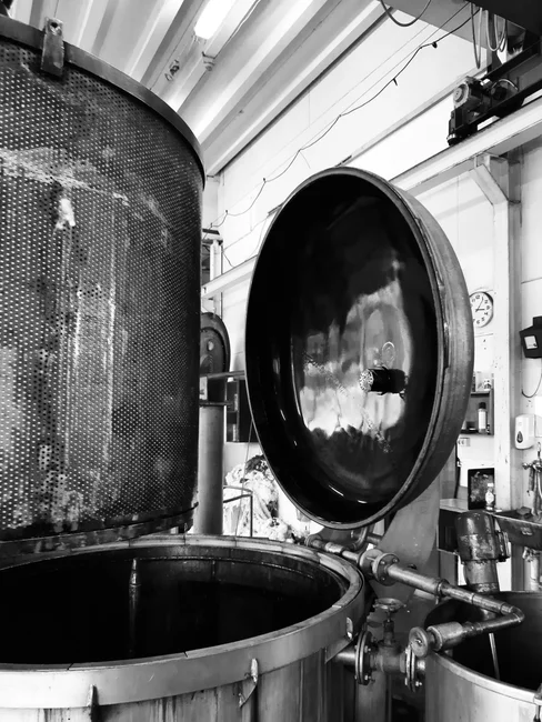
The 2026 reference train for an enzyme plant producing 20–200 m³/d of wastewater runs through five unit operations, each of which has to be specified against the pollutant envelope above rather than a generic industrial template.
Stage 1 — Equalisation and neutralisation. A balance tank sized for 8–24 h hydraulic retention dampens batch pH swings (2–11) and flow peaks. PLC-controlled chemical dosing for pH correction and polymer feed is used at the outlet to hold the mixed stream inside the 6.5–8.0 band the aeration basin needs.
Stage 2 — Primary clarification / DAF. A DAF unit for free oil, antifoam, and floating mycelia removal cuts TSS by 60–80% and removes the inhibitory floatables before biology. Plants with limited footprint substitute a lamella clarifier, accepting 40–60% TSS removal in exchange for a smaller civil envelope. Existing assets are often retrofitted in 2026 rather than replaced — see the field-tested guidance on DAF retrofit triggers and upgrades.
Stage 3 — Biological treatment. Either conventional activated sludge (CAS) at 15–25 day SRT or a submerged MBR. An MBR with PVDF flat-sheet membranes is the default where discharge limits are tight or where the site cannot afford the footprint of a clarifier.
Stage 4 — Sludge thickening. Waste activated sludge (WAS) is thickened to 2–4% DS by DAF or gravity, depending on antifoam loading and downstream press selection.
Stage 5 — Mechanical dewatering. Polymer-conditioned sludge is fed to a plate-and-frame filter press for biosolids dewatering for 22–28% DS cake, or a belt press for 18–22% DS at higher hydraulic throughput. The submerged MBR with PVDF flat-sheet membranes upstream sharply improves downstream sludge filterability; operating guidance for keeping those membranes clean is covered in MBR membrane fouling prevention strategies.
CIP waste, fermenter bleed, and antifoam rinses should be kept segregated at source where possible so each can be conditioned before mixing. The combined stream is what determines aeration tank volume; the segregated solids streams determine polymer dose and press cycle.
Biological Treatment Sizing Parameters
The aeration basin at an enzyme plant is sized tighter than a municipal design, not looser, because the F/M ratio has to stay low enough to give the antifoam-degrading fraction of the biomass a competitive advantage over faster-growing heterotrophs. The numbers below are the working values used in 2026 EPC specs for plants in the 20–200 m³/d range (HydropureWater field data, 2026).
| Parameter | CAS | MBR |
|---|---|---|
| SRT (days) | 15–25 | 20–40 |
| HRT (hours) | 24–36 | 18–30 |
| MLSS (mg/L) | 4,000–6,000 | 8,000–12,000 |
| F/M (kg BOD/kg MLSS·d) | 0.10–0.20 | 0.08–0.15 |
| Dissolved oxygen (mg/L) | 1.5–2.5 | 1.5–2.5 |
| Membrane pore size | n/a | 0.1 μm (PVDF) |
SRT is the single most important variable. Below 15 days, nitrification collapses and antifoam residues pass through largely undegraded; above 25 days in CAS, the basin is oversized for the loading and endogenous decay starts to dominate the sludge yield. MBR designs tolerate higher SRT (up to 40 days) because membrane separation decouples the clarifier overflow from mixed-liquor concentration.
Long SRT operation aligns with the academic precedent on sludge-age control for inhibitory substrates: extended mean cell residence time is the lever that selects for slow-growing specialists capable of metabolising the silicone polyol and trace-solvent fraction of the feed. The trade-off is excess sludge with high endogenous residue and lower dewaterability, which is why the thickening and pressing stages downstream have to be specified with that sludge character in mind rather than municipal numbers.
Sludge Thickening and Dewatering Equipment Compared
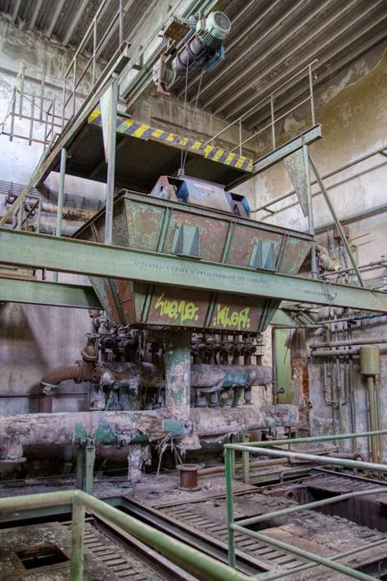
The thickening and dewatering choice is where most enzyme plant ETP projects either save or lose 15–25% of lifecycle cost, because polymer consumption, cake transport, and disposal surcharges all flow from this decision. The table compares the five configurations an engineer is likely to evaluate in 2026 (HydropureWater field data, 2026).
| Equipment | Output DS (%) | Solids capture (%) | Polymer (kg/t DS) | Footprint | Best fit |
|---|---|---|---|---|---|
| Gravity thickener | 2–3 | 80–90 | 0–1 | Large | Hydraulic load >50 m³/h, low antifoam |
| DAF thickener | 3–5 | 85–95 | 2–4 | Compact | Oily / floating fractions, enzyme plants |
| Centrifuge | 4–6 | 90–95 | 3–6 | Compact | Frequent product changeovers, variable feed |
| Belt press | 18–22 | 92–96 | 4–8 | Medium | Continuous throughput, lower CAPEX |
| Plate-and-frame filter press | 22–28 | 90–95 | 3–8 | Medium | Landfill / incineration cake, 2026 default |
DAF thickening is the most common choice upstream of a press at enzyme plants because it copes well with the antifoam and floating mycelia that defeat gravity thickeners. A plate-and-frame filter press for biosolids dewatering in the 1–500 m² range is the 2026 default for plants sending cake to landfill or incineration, because 22–28% DS avoids the leachate penalty surcharges most EU and US landfills apply below 20% DS. Belt presses win on continuous throughput and lower CAPEX but lose on cake dryness and polymer demand. Selection guidance specific to Southeast Asian greenfield builds is laid out in the sludge dewatering machine selection buyer's guide for 2026.
Polymer Conditioning and Cake Dryness Targets
Conditioning is the step that decides whether the downstream cake clears landfill acceptance criteria. Cationic polyacrylamide (CPAM) at 3–8 kg dry polymer per dry tonne of solids is the working range for enzyme plant biological sludge (HydropureWater field data, 2026). Dose climbs toward the upper bound when antifoam loading is high or when the upstream SRT has drifted below 15 days and the sludge is rich in extracellular polymer.
The cake dryness target of 22–28% DS is set by the disposal route, not by the press itself. Most EU landfills apply a surcharge below 20% DS to recover leachate treatment cost, and a similar pattern is spreading in 2026 across US jurisdictions. Incineration with energy recovery becomes economically viable only above ~22% DS, because below that the autothermal ignition point cannot be sustained without auxiliary fuel. Filter press cycle time of 2–4 h — covering filling, pressing at 7–15 bar, and cake discharge — typically drives press sizing more than plate area alone, and is the value to defend in a design review.
Compliance, Reuse, and Biosolids Disposal in 2026
Equipment selection and the CAPEX/OPEX decision converge at the discharge point. Three destinations are realistic for a 2026 enzyme plant, and the train spec above maps to each one as follows.
Sewer discharge (pretreatment). Most pretreatment ordinances require COD below 1,000–1,500 mg/L and TSS below 200–500 mg/L at the plant outlet. A CAS train plus DAF polishing is usually sufficient; an MBR is only justified when the local limit tightens. Sludge is dewatered to 22–28% DS and sent to landfill as biosolids.
Surface water discharge. Limits tighten to COD below 125 mg/L and TSS below 35 mg/L in most jurisdictions (per EU Urban Wastewater Treatment Directive 91/271/EEC as updated through 2025). MBR is the 2026 default here, often with a tertiary polish step. Dewatered cake route is the same as above.
Biosolids disposal in 2026. Landfill remains the most common route for pressed cake. Incineration with energy recovery is growing in capacity-constrained regions, especially in Western Europe and Japan, where gate fees for landfill are high. Land application is permitted in some US states and EU member states only after metals and pathogen screening, and is rarely used for enzyme plant biosolids because of the residual nitrogen loading.
An emerging circular-economy route is the use of dewatered industrial sludge as a low-cost fermentation substrate for further enzyme production, demonstrated in recent academic work on industrial sludge valorisation. The route is viable only where the plant has a co-located fermentation line that can accept variable substrate, and it is treated as an optional disposal pathway rather than the design basis in 2026.
The CAPEX/OPEX decision framework reduces to a simple rule: small plants (<50 m³/d) sewer-discharging should default to CAS plus DAF plus plate-and-frame press; mid-sized plants (50–200 m³/d) with surface water discharge should default to MBR plus plate-and-frame press; large plants (>200 m³/d) should evaluate centrifuge pre-thickening against DAF pre-thickening on a 10-year lifecycle basis, with cake disposal gate fee as the dominant variable.
Frequently Asked Questions
What SRT is needed to treat antifoam in enzyme plant wastewater?
A 15–25 day SRT in conventional activated sludge is the working range for acclimating the biomass to silicone- and polyol-based antifoam; below 15 days the inhibitory fraction passes through largely intact and polymer demand downstream rises sharply. MBR designs at 20–40 day SRT are more robust against antifoam breakthrough but produce more endogenous sludge.
Which dewatering equipment gives the driest cake for enzyme plant biosolids?
A plate-and-frame filter press operated at 7–15 bar delivers 22–28% DS cake with 90–95% solids capture, which is the typical 2026 target for landfill acceptance and incinerator autothermal operation. Belt presses stop at 18–22% DS and are used where continuous throughput and lower CAPEX outweigh the cake-transport penalty.
What is the typical polymer dose for conditioning enzyme plant biological sludge?
Cationic polyacrylamide at 3–8 kg dry polymer per dry tonne of solids is the standard 2026 range for waste activated sludge from enzyme plant MBR or CAS trains. Dose climbs toward 8 kg/t DS when antifoam loading is high or when upstream SRT has drifted below 15 days.
Can enzyme plant biosolids be land-applied in 2026?
Land application is permitted in some US states and EU member states after metals and pathogen screening, but is rarely used for enzyme plant cake because of the residual nitrogen load and the variability of the substrate. Landfill and incineration with energy recovery remain the dominant 2026 disposal routes.
How much space does an MBR save versus CAS for an enzyme plant?
An MBR with 8,000–12,000 mg/L MLSS typically halves the aeration basin volume of a 4,000–6,000 mg/L CAS design for the same loading, and eliminates the secondary clarifier. The trade-off is membrane replacement cost, which is why MBR membrane fouling prevention strategies are a material part of the OPEX model.
Related Equipment
- plate-and-frame filter press for biosolids dewatering — specifications, capacity range, and technical data