
Why Fairfield semiconductor fabs are re-evaluating CAS in 2026
A Fairfield fab's wastewater mix in 2026 is not a municipal sewage problem with a few exotic ions sprinkled in — it is a multi-stream industrial matrix that defeats biology if upstream chemistry is wrong. Hydrofluoric acid etching generates fluoride at concentrations up to 2,000 mg/L in segregated side streams; chemical-mechanical polishing (CMP) sends copper-bearing slurry into the drain at 50-500 mg/L Cu and produces TSS spikes from 100 mg/L baseline to more than 1,000 mg/L within minutes. Tetramethylammonium hydroxide (TMAH) from photoresist developers adds a recalcitrant organic at 10-100 mg/L, while isopropanol, acetone and NMP from solvent benches push COD swings from 200 to 2,000 mg/L on a single shift cycle. RCA cleans add NH3-N at 20-80 mg/L. Treating that stream as a generic biology problem is exactly how 2025 permit excursions happened at peer fabs in Santa Clara and Tualatin.
The regulatory pressure in 2026 is the second driver. Solano Sanitation District's industrial pretreatment program tightened local limits on copper (typically 1.0-2.0 mg/L daily max), fluoride (typically 25-50 mg/L daily max), and total nitrogen (NH3-N plus nitrate, often 10-25 mg/L), with a TSS ceiling of 30 mg/L for non-reuse discharge. At the same time, fab corporate water-reuse targets have moved the recovery envelope from ~60% to 75-80%, which means the discharge limit is no longer the only number the biological train has to hit — the permeate also has to feed RO without fouling in three weeks. Mannina et al. (2019) found CAS direct GHG emissions of 0.85 kgCO2eq/m3 versus 0.91 for MBR on a plant-wide basis, so activated sludge is not the environmental villain; the question is whether the clarifier overflow can meet both the POTW limit and the RO feed spec at the same time.
The third driver is the pad. Most Fairfield fabs were built in the late 1990s to early 2000s on constrained sites between I-80 and Travis AFB, so the activated-sludge basin and the equalisation tank are already there. A green-field biological replacement is rarely an option, which is why retrofit decisions — keep CAS, drop in an MBR, or run both in series — are the only real choices on the table.
What conventional activated sludge actually does to a fab stream
A standard CAS train at a fab runs in this order: equalisation → pH adjustment → fluoride precipitation with CaCl2 → coagulation/clarification → aeration basin (SRT 5-15 days, MLSS 2,500-4,000 mg/L) → secondary clarifier → sand filter → carbon filter → discharge or RO. On the fab's organic load — IPA, acetone, TMAH, low-MW surfactants — CAS typically removes 85-95% of BOD and COD when the basin is not in shock. The biology is well understood, the local Fairfield wastewater operator pool is already trained on it, and the spare-parts inventory is generic.
The failure modes at a fab are not generic municipal failure modes. First, clarifier upsets after a CMP dump: when TSS in the aeration basin feed jumps from ~100 mg/L to more than 1,000 mg/L within minutes because a polishing-tool change routed slurry down the wrong header, the clarifier blankets rise and TSS in the overflow climbs from a baseline of 10-30 mg/L to more than 100 mg/L for 4-8 hours. Second, copper shock at 50-500 mg/L Cu inhibits nitrifiers; NH3-N in the effluent can rise from <2 mg/L to 15-30 mg/L within 24 hours and recover only over a full SRT. Third, fluoride residuals pass through the biological step essentially unchanged — the 0.85 kgCO2eq/m3 GHG profile (Mannina et al., 2019) does nothing for an ion — and any residual above the local limit will be flagged in the next POTW compliance sample.
The practical question for a process engineer auditing an existing train is: is the bottleneck the aeration basin, the clarifier, or the upstream chemistry? If the fluoride is still >50 mg/L after CaCl2 precipitation, the biology is not the problem and MBR will not fix it. If the clarifier overflow TSS is the failure, that is an MBR candidate. If the aeration basin itself cannot nitrify, both systems need a biology upgrade first.
What an MBR changes — and what it doesn't
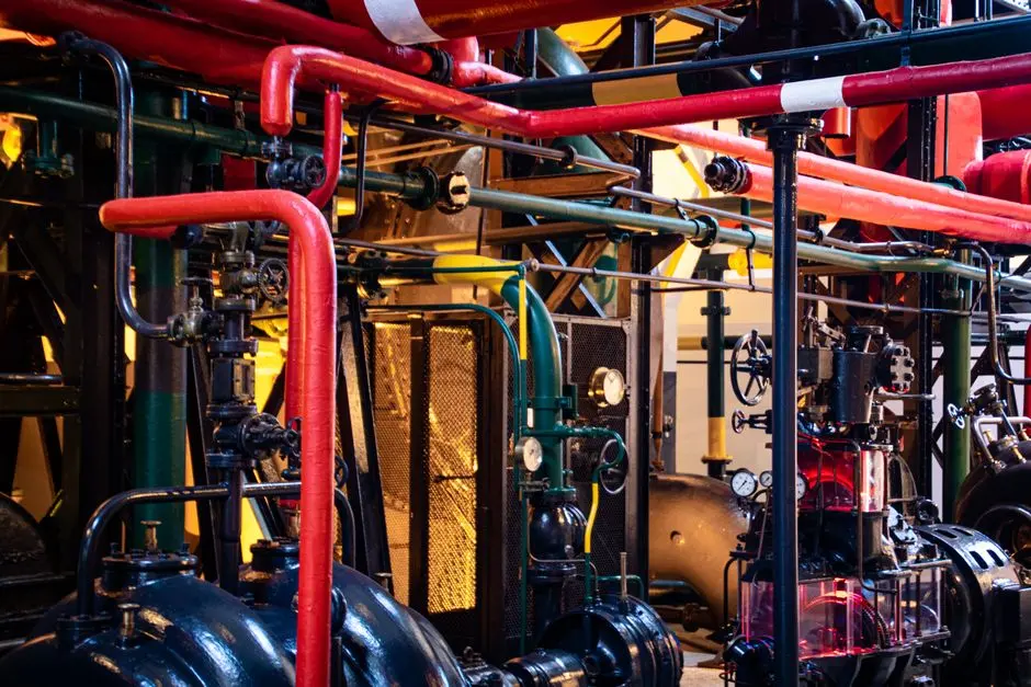
An MBR is a solid-liquid separation upgrade, not a chemistry fix. A submerged PVDF flat-sheet or hollow-fibre cassette at 0.04-0.2 µm pore size (the cut-off range documented for MBR modules in Grasmick et al., 2012) replaces the secondary clarifier entirely. The membrane is installed directly in the aeration tank or in a separate membrane tank, biomass is retained at SRT 20-60 days and MLSS 8-12 g/L, and the permeate flows out under low suction (typically -5 to -30 kPa transmembrane pressure). Because no floc separation step is required, the clarifier overflow problem disappears.
What the membrane actually delivers: effluent TSS typically <5 mg/L and turbidity <1 NTU — confirmed in the 0.04-0.2 µm cut-off range — which is directly compatible with an RO feed without intermediate polishing. The higher SRT (20-60 days versus 5-15 for CAS) gives more stable nitrification across CMP copper shocks, because the slower-growing nitrifiers stay in the basin and the system has more biomass buffering. Bertanza et al. (2017), as summarised in the Mannina et al. (2019) plant-wide study, also reported that MBR effluent has lower microplastic counts (0.4 MP/L) than CAS effluent (1 MP/L).
What the membrane does not deliver: fluoride ions pass straight through a 0.1 µm PVDF membrane because the cut-off is on particles, not ions — CaCl2 precipitation or ion exchange is still mandatory upstream. Dissolved copper ions behave the same way; only particulate copper is physically retained. The operating penalty is real: membrane fouling forces continuous air-scour and periodic chemical CIP (typically 300-500 mg/L NaOCl for organics, then 1-2% citric acid for scalants), and submerged flat-sheet configurations still use 10-20x more energy for aeration than an equivalent CAS basin, even though they are far cheaper to run than external cross-flow MBRs.
MBR vs CAS head-to-head: the parameters that matter at a fab
The table below scores the two systems on the parameters a Fairfield fab actually cares about. Numbers are anchored to published data where a figure exists; fab-specific rows are called out separately because the MBR vs CAS comparison as a biology question is the wrong frame for this industry.
| Parameter | Conventional Activated Sludge (CAS) | Submerged MBR (PVDF flat-sheet) |
|---|---|---|
| Effluent TSS | 10-30 mg/L (clarifier-dependent) | <5 mg/L consistently |
| Effluent turbidity | 5-15 NTU | <1 NTU |
| Effluent COD / BOD | 85-95% removal on fab organics | 90-98% removal; more stable under CMP shock |
| NH3-N removal | Stable at SRT 5-15 days; vulnerable to Cu shock | Stable at SRT 20-60 days; recovers within hours after Cu pulse |
| Fluoride removal (F-) | None — passes through to clarifier overflow | None — passes through membrane; upstream CaCl2 required for both |
| Copper removal (dissolved Cu) | Biological only; nitrification inhibited at 50-500 mg/L Cu | Particulate Cu retained; dissolved Cu still needs sulfide or hydroxide precipitation |
| Footprint | Baseline (100%) | ~40% of equivalent CAS train (Judd, 2010) |
| SRT | 5-15 days | 20-60 days |
| MLSS | 2,500-4,000 mg/L | 8,000-12,000 mg/L |
| Direct GHG emissions | 0.85 kgCO2eq/m3 (Mannina et al., 2019) | 0.91 kgCO2eq/m3 (Mannina et al., 2019) |
| Energy demand | 0.3-0.5 kWh/m3 for aeration | 0.8-1.5 kWh/m3 including air-scour and CIP pumps |
| OPEX band (fab scale, 500 m3/day) | USD 0.25-0.45/m3 treated | USD 0.45-0.75/m3 treated, dominated by membrane replacement every 7-10 years |
| Membrane-fouling risk | Not applicable | CIP every 1-3 months; cassette replacement every 7-10 years |
| Effluent microplastics | ~1 MP/L (Lares et al., 2018) | ~0.4 MP/L (Lares et al., 2018) |
| Fab-specific verdict on F- and Cu | Both failures must be solved upstream in equalisation/precipitation regardless of biology choice | Same upstream chemistry is mandatory; the membrane only changes downstream TSS and reuse readiness |
The last row is the one most top-3 pages miss. The MBR vs CAS debate at a fab collapses to a single insight: the membrane is a physical barrier on particulates, not a chemistry reactor. If a fab is still trying to meet its fluoride and copper limits by adjusting aeration or SRT, the problem is upstream and no biological retrofit will save it.
When CAS is still the right answer in 2026
CAS is the right call when the fab discharges to the Solano Sanitation District under an industrial pretreatment permit, has no RO reuse target above ~50%, and the existing basin is in good mechanical condition. The 0.85 kgCO2eq/m3 direct GHG figure from Mannina et al. (2019) means CAS is also the lower-energy, lower-OPEX option on a pure discharge-to-POTW basis — the local Fairfield operator pool already knows how to run it, spare parts are off-the-shelf, and clarifier upsets after a CMP dump are recoverable inside one SRT with a controlled waste.
CAS also handles organic shock loads better than MBR in one specific way: when an IPA or acetone slug wipes out biomass, a clarifier can be dumped and reseeded from a healthy neighbouring basin within hours; an MBR cassette cannot be reseeded on the same time scale because the membrane tank has to be drained, cleaned, and restarted. For a fab with variable upstream chemistry and conservative EHS posture, that operational flexibility is worth more than the 15-20 mg/L TSS improvement an MBR delivers. CAPEX is the third argument: a CAS retrofit runs roughly 40-60% of an MBR retrofit on the same hydraulic capacity (Karim & Mark, 2017, summarised in the Mannina et al. 2019 review), and Karim & Mark found MBR becomes the lowest total-cost option only beyond ~67 years of continuous service — a horizon few fabs plan for. For a fab that simply needs a packaged biological step to sit in front of a discharge, the integrated packaged sewage treatment unit is a credible bolt-in.
When MBR is the right answer — and what to retrofit first
MBR is the right call when the fab is targeting 75-80% water reuse, when the existing secondary clarifier is at hydraulic limit, or when TSS to the RO unit must hold below 5 mg/L consistently without a sand-filter polish. In retrofit terms the change is smaller than it looks: keep equalisation, pH adjustment, fluoride precipitation with CaCl2, and the primary clarifier; convert one of two existing CAS basins into an MBR tank; install submerged flat-sheet cassettes sized to the peak day flow; add a low-pressure RO polish on the MBR permeate.
The cassette selection matters more than the tank civil work. A DF-series 0.1 µm PVDF flat-sheet MBR cassette in the 32-135 m3/day per module range is the typical building block for the membrane step, and the integrated aeration box on submerged flat-sheet designs is the reason these systems use 10-20x less energy than external cross-flow MBRs while still delivering the <1 µm permeate spec. The full integrated MBR system with submerged PVDF membranes ties the cassette, blowers, permeate pumps, CIP skid and control panel into a single skid that drops into a converted CAS basin in 4-6 weeks of civil work plus commissioning.
Two sequencing rules from fab retrofits in the field. First, do the upstream chemistry (CaCl2 dosing, pH control, fluoride mass balance) before the membrane arrives; an MBR cannot fix a chemistry problem. Second, leave the second CAS basin in place as a bypass / re-seed source for the MBR during the first 6-12 months while the biology stabilises.
Decision framework: CAS, MBR, or hybrid at a Fairfield fab
Use this four-branch decision tree in the next project meeting. It is written to the actual discharge options a Fairfield fab faces in 2026, not to a textbook biology question.
- Discharge to POTW, no reuse target: keep CAS, focus OPEX on clarifier reliability, fluoride precipitation with CaCl2, and equalisation buffer sizing for CMP dumps. Add a sand/carbon polish if TSS variability is the only failure mode.
- Reuse target 50-70%: add an MBR polish on one CAS basin, send MBR permeate to a low-pressure RO. The existing CAS basin handles the bulk BOD/COD load and the MBR delivers the RO-grade TSS spec.
- Reuse target >75% or pad expansion needed: full MBR conversion, abandon the secondary clarifier, run RO on MBR permeate, and add an industrial RO unit for fab water reuse with a CaCl2 and NaOH dosing skid upstream to keep the membrane within its scaling envelope.
- Always run a fluoride mass balance first. If fluoride exceeds ~50 mg/L after CaCl2 precipitation, MBR will not save you — add ion exchange or RO. The upstream chemistry work is described in the semiconductor CMP wastewater treatment guide and the silicon-wafer hybrid process design with 99.8% recovery; the biological comparison here assumes those steps are already in place.
Frequently Asked Questions
Does MBR remove fluoride from fab wastewater?
No. The 0.04-0.2 µm PVDF membrane is a particulate barrier, not an ion-exchange medium. Fluoride passes through the membrane essentially unchanged; it must be precipitated as CaF2 with CaCl2 upstream, or polished by ion exchange or RO. A fab that adds an MBR without first hitting <25-50 mg/L fluoride in the equalisation tank will not see a different fluoride number in the permeate.
Can an MBR handle copper from CMP wastewater?
Partially. The membrane retains particulate copper and most colloidal copper bound to floc, but dissolved Cu2+ passes through at the same concentration as the mixed liquor. A copper pulse of 50-500 mg/L will still inhibit nitrification, although MBR biomass at SRT 20-60 days recovers faster than CAS at SRT 5-15 days. For dissolved copper removal, the fab still needs a hydroxide or sulfide precipitation step upstream of the MBR tank.
What is the typical SRT for an MBR at a semiconductor fab?
20-60 days is the operating window for a submerged flat-sheet MBR at fab loading, versus 5-15 days for CAS. The longer SRT is the reason MBR nitrification is more stable across CMP copper shocks and why the basin can absorb a 100 to >1,000 mg/L TSS slug from a polishing-tool change without losing the biomass.
How much does an MBR retrofit cost at a Fairfield fab?
Order-of-magnitude USD 80-180 per m3/day of installed capacity for a 500 m3/day retrofit, with the membrane cassette and the downstream RO polish as the two main cost drivers. Civil work is minor if an existing CAS basin is being repurposed. Membrane replacement every 7-10 years is the largest OPEX line item.
Is MBR worth it versus CAS for a fab that does not need reuse?
No. If the discharge path is to the Solano Sanitation District under an industrial pretreatment permit and the reuse target is below ~50%, CAS plus a clarifier and a sand/carbon polish is the lower-CAPEX, lower-OPEX path, and the Mannina et al. (2019) GHG figures confirm CAS is also the lower-energy option. MBR earns its premium only when the permeate has to feed RO or the clarifier is at hydraulic limit.