Why Richmond chemical plants are revisiting the DAF-vs-clarifier question in 2026
Richmond's industrial corridor from Hopeman Road down to the James River is not a generic chemical-sewer site. It mixes polymer production, specialty batch chemicals, resin manufacturing, and chlor-alkali side-streams, and that mix generates a stream profile that sits between the food-grade FOG case most DAF articles assume and the dense metal-hydroxide case we covered in the DAF vs clarifier for mining wastewater in 2026 piece. Emulsified solvent, polymer latex, and intermittent brine discharges are the everyday reality here, and the existing gravity clarifiers on a lot of these sites are 1970s-era rectangular tanks that bleed TSS on every batch cycle.
The discharge envelope compounds the pressure. Most Richmond chemical sites discharge under a VPDES permit issued by Virginia DEQ through 9VAC25-31, and pretreatment sites flow into the Henrico County Department of Public Utilities industrial pretreatment program, which administers the local limits for oil and grease, TSS, and metals that sit on top of the federal envelope. The cap on oil and grease at 100 mg/L daily maximum and 50 mg/L monthly average is the line that flips a clarifier-only design into a permit risk every time a reactor seal pot pushes a slug of solvent into the sewer. The 2026 capital cycle is forcing the timing: ESG-driven water-reuse targets, board-level net-zero water commitments, and a single 2025 batch upset that triggered a Henrico pretreatment violation have moved primary clarifier replacement from a maintenance line item to a capital justification memo.
This article lays out a stream-property-driven decision framework for a Richmond chemicals plant choosing between dissolved air flotation and a lamella clarifier, anchored to 9VAC25-31 and the local pretreatment program, and sized to a 100 m³/h chemical stream. It is the chemicals-specific iteration of the three-rule framework (FOG band, floc density, cold weather) used in the mining piece, re-tuned for emulsions, viscosity, and TDS rather than tramp oil and hydroxide floc. The same logic also extends to the parallel DAF vs clarifier for API and formulation pharma wastewater in 2026 discussion at higher stream temperatures.
What a chemicals wastewater stream actually looks like in Richmond
A working chemicals stream for a 2026 Richmond design typically runs 200–1,500 mg/L TSS, 30–300 mg/L FOG and emulsified solvent, 500–5,000 mg/L COD, and pH that swings 2–12 across batch cycles. TDS is the wild card: most streams sit in the 1,000–3,000 mg/L range, but brine side-streams from chlor-alkali or ion-exchange regeneration push 5,000–10,000 mg/L on a daily basis, and that is the single biggest deviation from the food-grade FOG case the rest of the DAF literature assumes.
Particle character is heterogeneous. Polymer latex, resin fines, and catalyst carryover create a mix of colloidal and settleable solids, and floc density depends on which upstream chemistry the plant has standardized. Alum-conditioned floc tends to be light and fluffy, PAC-conditioned floc is denser and easier to float or settle, and ferric-conditioned floc is the densest of the three. The floc density drives Rule 2 in the next section.
Emulsion is the problem a clarifier cannot solve. Solvent carryover, lube from reactor seal pots, and surfactant residuals from cleaning-in-place cycles produce stable emulsions with droplet sizes under 20 µm. Those droplets do not break in the 1–2 hour residence time of a clarifier; they exit in the overflow and land on the outfall. For chemical-plant wastewater, FOG includes both free oils and emulsified solvent or polymer residuals; the 50 mg/L FOG decision band from the 2026 mining framework transfers to chemicals as the boundary above which a lamella-only is not defensible.
Variable load is the operational reality. Batch reactors discharge on a cycle, not continuously, so the primary clarifier must handle slug loads of 2–3x average flow without bleeding solids on the overflow. That is the structural reason conventional gravity clarifiers at 1–2 m/h surface loading are rarely the 2026 answer: they do not absorb a slug without a 500–800 m² footprint, and that footprint is rarely available inside an existing civil envelope.
| Parameter | Typical Richmond chemicals stream | Brine side-stream | Note |
|---|---|---|---|
| TSS | 200–1,500 mg/L | 100–200 mg/L | Polymer floc / resin fines / catalyst carryover |
| FOG / emulsified solvent | 30–300 mg/L | 0–10 mg/L | Reactor seal pot lube, cleaning-cycle solvents |
| COD | 500–5,000 mg/L | 200–1,000 mg/L | Spikes on batch discharge |
| TDS | 1,000–3,000 mg/L | 5,000–10,000 mg/L | Brine side-stream at chlor-alkali or IX regen |
| pH | 2–12 swings | 6–9 | Equalization basin typically required |
| Flow pattern | Batch, 2–3x slug | Semi-continuous | Sizing margin on hydraulic capacity |
How DAF and clarifiers actually separate solids — the mechanism that drives the choice
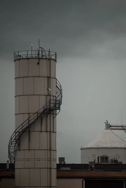
DAF floats solids using micro-bubbles generated from a pressurized recycle stream. Clarified water is drawn off the DAF outlet, pressurized to roughly 6 bar (87 psi), and saturated with air in a packed saturation vessel. When the saturated recycle is depressurized back into the flotation tank at atmospheric pressure, dissolved air comes out of solution as 30–50 µm bubbles (per S1, S4). Those bubbles attach to chemically conditioned floc and lift it to the surface, where a skimmer sweeps the float into a sludge trough; clarified water exits below the float blanket. Removal performance is >90% for TSS, FOG, COD, and BOD when the upstream chemistry is right (per S4, S5). The DAF chemistry window is PAC 10–30 mg/L or ferric chloride plus anionic polymer 1–5 mg/L; without that conditioning, micro-bubbles pass right past colloidal fines and DAF underperforms. For a Richmond chemicals plant, a packaged HydropureWater DAF system sized to the upper FOG band handles a reactor upset upstream so the downstream lamella is not asked to do chemistry it cannot do.
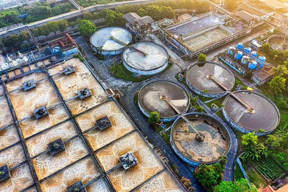
A lamella clarifier stacks inclined plates inside a compact tank. The plates multiply effective settling area, so surface loading climbs to 20–40 m/h and footprint drops to 0.3–0.6 m² per m³/h, roughly an order of magnitude below a conventional clarifier at the same flow. Many lamella designs include a sludge-recirculation loop that re-injects settled sludge to contact fresh influent, cutting coagulant consumption by up to 30%. A packaged HydropureWater lamella clarifier in this service class handles 100 m³/h in 50–60 m² of plate-pack footprint. The 20–40 m/h band, however, is for clean, well-conditioned hydroxide floc; for light polymer or latex floc the design surface loading drops to 10–15 m/h to avoid shearing and TSS carryover.
A conventional gravity clarifier operates at 1–2 m/h surface loading and 5–8 m² per m³/h footprint, the structural reason it is rarely the 2026 answer for a Richmond chemical plant replacing legacy infrastructure inside a tight civil envelope. Most 1970s rectangular clarifiers on Richmond chemical sites run out of hydraulic capacity at 2x average flow and bleed solids on the first batch upset of the week.
The three rules for choosing DAF or a clarifier on a chemicals stream
Rule 1 — Emulsion and FOG first. Free oil and emulsified solvent do not settle in a clarifier's residence time; they exit in the overflow and land on the outfall. Any emulsified solvent, lube from seal pots, or polymer latex above 50 mg/L forces DAF upstream or as a polish step. A lamella cannot recover oil that floats. The bands that show up in Richmond bid documents run 30 mg/L background (tramp lube from seal pots), 50 mg/L intermittent (cleaning-cycle discharge), and 100 mg/L active (reactor upset or polymer-latex breakthrough). Crossing 50 mg/L is the band where lamella-only stops being defensible against 9VAC25-31 daily-maximum oil and grease limits. A HydropureWater DAF system sized on the upper end of that band handles the upset load upstream.
Rule 2 — Floc density. Conditioned floc with specific gravity above 1.05 settles readily and favors a lamella; the same polymer-conditioned floc also binds tightly to 30–50 µm micro-bubbles and floats cleanly in a DAF (per S2, S4). When upstream chemistry is right, either mechanism works on dense floc, so the choice depends on the stream property Rule 1 has not already decided. The parallel TSS band on the upstream clarifier overflow is the second trigger: hold TSS below 30 mg/L and lamella-only is defensible; 30–50 mg/L means a polish step is needed; above 100 mg/L the lamella is overloaded and DAF should move upstream. This is the same band structure used in the mining piece, retuned for polymer and resin floc.
Rule 3 — Temperature and viscosity rather than cold weather. Chemical reactors often run hot, but a Richmond winter drop to 5°C thickens water and slows settling; micro-bubble nucleation kinetics slow 20–30% at 5°C versus 20°C (HydropureWater field data, 2026), so a 10–15% sizing margin on the recycle pump and saturation vessel is prudent. The same rule applies more gently to a lamella: low temperature thickens water and slows settling slightly, but the dominant cold-climate risk for an unheated lamella vault is sludge-hopper freeze, not kinetics drift. High-TDS brine side-streams from chlor-alkali or ion-exchange regeneration reduce bubble attachment efficiency; a coagulant switch to ferric chloride plus a low-charge anionic polymer typically restores DAF performance on those streams.
| Rule | Trigger band | Decision | Notes |
|---|---|---|---|
| Rule 1 — Emulsion / FOG | < 30 mg/L: lamella defensible. 30–50: monitor. > 50: DAF primary. > 100: DAF non-negotiable. | FOG or emulsified solvent decides the train first | 9VAC25-31 daily-max O&G 100 mg/L |
| Rule 2 — Floc density / TSS overflow | Overflow < 30 mg/L TSS: lamella defensible. 30–50: polish needed. > 100: DAF upstream. | Specific gravity > 1.05 favors settling; the same floc also floats in DAF | PAC, ferric, or alum conditioned |
| Rule 3 — Temperature and viscosity | Winter 5°C vs summer 20°C | +10–15% sizing on DAF recycle and saturation vessel; heat-trace lamella vault | Bubble nucleation slows 20–30% at 5°C |
| Add-on — High-TDS brine | TDS > 5,000 mg/L | Switch to ferric + low-charge anionic; expect reduced bubble attachment | Chlor-alkali and IX regeneration side-streams |
DAF vs lamella: the parameter table procurement will ask for
The matrix below reorganizes the engineering numbers procurement will request in the RFQ, drawn from HydropureWater field data (2026) and the parallel mining-piece references. Use it as the starting point for vendor clarification; verify every line against site-specific jar testing and the current VPDES permit.
| Parameter | DAF | Lamella clarifier | Conventional gravity clarifier |
|---|---|---|---|
| TSS removal on conditioned floc | > 90% | 70–90% | 50–70% |
| FOG / emulsified solvent removal | > 90% | Near zero (oil floats, exits overflow) | Near zero |
| COD removal | > 80% | 50–70% | 40–60% |
| Footprint at 100 m³/h | 0.2–0.4 m² per m³/h (20–40 m²) | 0.3–0.6 m² per m³/h (30–60 m²) | 5–8 m² per m³/h (500–800 m²) |
| Equipment CAPEX multiplier (lamella = 1.0x) | 1.5–2.5x | 1.0x | 0.6–0.8x (plus heavy civil) |
| Energy | 8–15 kWh/m³ (compressor + recycle) | 0.1–0.3 kWh/m³ (scraper drive) | 0.1–0.3 kWh/m³ |
| Chemical use | PAC 10–30 mg/L + anionic polymer 1–5 mg/L | PAC 10–30 mg/L + polymer 1–5 mg/L; up to 30% less via sludge recycle | PAC 10–30 mg/L + polymer 1–5 mg/L |
| Float / sludge dryness | Float 4–8% DS — direct to filter press | Underflow 2–5% DS — needs thickener upstream of press | Underflow 1–3% DS |
| FOG / emulsion capture | Primary function | Cannot recover floating oil | Cannot recover floating oil |
| Cold-weather performance (< 10°C) | Moderate — size +10–15% margin | Low (sludge-hopper freeze risk) | Low (same freeze risk, larger vault) |
| Sludge handling | Float feeds a plate-and-frame filter press directly | Underflow needs thickener upstream of the press | Underflow needs thickener |
Two pieces of kit make the 2026 cost band defensible in front of procurement: an automatic chemical dosing skid to hold coagulant and polymer within the design window, and a plate-and-frame filter press sized to either the DAF float or the lamella underflow. Both are visible line items on the RFQ, and both move the answer more than the choice of clarifier technology on its own.
Three Richmond chemical-plant scenarios and the technology each one picks
Scenario 1 — Specialty batch chemical plant, 60 m³/h, intermittent solvent emulsion. The stream runs 100–300 mg/L TSS and 50–200 mg/L emulsified solvent on cleaning cycles. DAF is non-negotiable as primary, a small lamella follows as polish for residual TSS to give margin against 9VAC25-31 daily-maximum limits. The 60 m³/h flow sits mid-band on a standard HydropureWater DAF system with no custom-engineering markup. A HydropureWater lamella clarifier downstream cuts residual TSS to the 20–30 mg/L band that gives compliance margin on the monthly-average envelope.
Scenario 2 — Polymer production plant, 200 m³/h, latex and surfactant residuals, no free oil. The stream carries 500–1,500 mg/L TSS as polymer floc and surfactant-stabilized colloids with specific gravity around 1.02. DAF primary because the surfactant-stabilized colloids do not settle in a lamella's residence time. A lamella polish keeps the overflow below 30 mg/L TSS. The 200 m³/h flow is large enough that the DAF footprint advantage over a conventional clarifier (200 × 8 = 1,600 m² versus 200 × 0.4 = 80 m²) dominates the building-cost math. An automatic chemical dosing skid is required because the polymer dose window is tight and the influent varies hour to hour.
Scenario 3 — Chlor-alkali brine side-stream, 25 m³/h, high TDS. The stream runs 5,000–10,000 mg/L TDS and 100–200 mg/L TSS as calcium-carbonate and magnesium-hydroxide precipitates. Lamella-only is defensible because floc specific gravity sits above 1.10 and there is no FOG; DAF is reserved as a polish step for upset events. Budget heat-tracing for the lamella vault to handle Richmond winter sludge-hopper freeze risk. The brine TDS reduces micro-bubble attachment efficiency enough that a ferric chloride plus low-charge anionic polymer combination is the standard chemistry, sized to the high-TDS side-stream rather than the bulk wastewater flow.
Cross-scenario note: all three meet 9VAC25-31 effluent limits with chemical precipitation plus the selected primary, but only Scenarios 1 and 2 carry FOG risk that makes a DAF-first process train the right 2026 answer. Scenario 3 is the lamella-only case that proves Rule 1 still works in reverse: no FOG, dense floc, lamella wins on CAPEX and energy.
| Scenario | Flow | Stream signature | Primary | Polish | Rule that decides |
|---|---|---|---|---|---|
| Specialty batch w/ solvent | 60 m³/h | 100–300 mg/L TSS, 50–200 mg/L emulsified solvent | DAF | Lamella | Rule 1 (FOG > 50 mg/L) |
| Polymer production | 200 m³/h | 500–1,500 mg/L TSS, latex, surfactant colloids (SG ~1.02) | DAF | Lamella | Rule 1 + Rule 2 (colloidal fines) |
| Chlor-alkali brine side-stream | 25 m³/h | 5,000–10,000 mg/L TDS, 100–200 mg/L TSS, no FOG | Lamella | DAF on upset | Dense floc (SG > 1.10), no FOG |
CAPEX, OPEX, and the 10-year economics for a Richmond chemical plant
Headline ratio: DAF CAPEX runs 1.5–2.5x a comparable lamella at equal flow (HydropureWater field data, 2026). That ratio narrows once civil work, excavation, and footprint-driven building costs are added. For a 100 m³/h Richmond stream, the footprint difference is roughly 30 m² of DAF versus 50–60 m² of lamella versus 500–800 m² of conventional clarifier, and in a dense industrial corridor that building-cost line item often flips the 10-year economics.
OPEX narrows the gap further. Both technologies use coagulant and polymer; the lamella saves up to 30% on coagulant via sludge recycle, but DAF produces a thicker float (4–8% DS) that dewaters more easily in a downstream plate-and-frame filter press versus a lamella underflow at 2–5% DS. The DAF's air compressor and recirculation pump are real line items at 8–15 kWh/m³, but they are a known scalable cost, not a contingency. The lamella runs 0.1–0.3 kWh/m³ on the scraper drive alone.
Two pieces of kit make the 2026 cost band defensible in front of procurement: an automatic chemical dosing skid to hold the dose within the design window, and a plate-and-frame filter press sized to either the DAF float (4–8% DS) or the lamella underflow (2–5% DS). For the chemicals stream, both pieces of equipment move the OPEX number more than the choice of clarifier technology on its own, because the dewatering step is what the haul-off cost depends on.
Board-level framing: a 2026 DAF or lamella at a Richmond chemical plant is rarely a greenfield decision. It is a replacement of a 1970s clarifier inside a tight civil envelope, which favors DAF primary plus lamella polish as the lowest-risk 10-year answer when FOG or emulsion is on the stream, and lamella-only as the lower-CAPEX answer on a brine side-stream with no FOG and dense settleable floc. The full industrial wastewater treatment engineering guide walks through a parallel cold-climate cost reconciliation in a different regulatory basin.
| Cost line | DAF | Lamella | Conventional clarifier | Notes |
|---|---|---|---|---|
| Equipment CAPEX at 100 m³/h | 1.5–2.5x baseline | 1.0x baseline | 0.6–0.8x baseline + heavy civil | Building cost often flips 10-year economics |
| Footprint at 100 m³/h | 20–40 m² | 30–60 m² | 500–800 m² | Richmond corridor is footprint-constrained |
| Energy | 8–15 kWh/m³ | 0.1–0.3 kWh/m³ | 0.1–0.3 kWh/m³ | Compressor and recycle pump dominate |
| Coagulant use | PAC 10–30 mg/L + polymer 1–5 mg/L | Up to 30% less via sludge recycle | Baseline | Lamella advantage on OPEX |
| Sludge to dewatering | Float 4–8% DS direct to filter press | Underflow 2–5% DS, needs thickener | Underflow 1–3% DS | DAF float dewatering is cheaper |
| 10-year replacement risk | Low — fits inside existing civil envelope | Low | High — usually requires new basin | Drives the 2026 capital cycle |
Frequently Asked Questions
Does Virginia DEQ 9VAC25-31 require a DAF or a lamella clarifier at a chemical plant?
No. 9VAC25-31 sets the effluent envelope, not the technology; oil and grease daily-maximum of 100 mg/L and monthly-average of 50 mg/L are the binding limits for most Richmond chemical sites. A well-sized DAF or lamella plus chemical precipitation can meet those limits, but FOG above 50 mg/L makes a clarifier-only design indefensible (per 9VAC25-31 and Henrico County pretreatment program).
What FOG or emulsified solvent level forces DAF upstream of a lamella?
Any sustained emulsified solvent or polymer-latex residual above 50 mg/L forces DAF primary. Below 30 mg/L background lube, lamella-only is defensible; 30–50 mg/L is the monitor band; above 100 mg/L a lamella-only will discharge the emulsion directly to the outfall and trip 9VAC25-31 daily-maximum oil and grease (per HydropureWater field data, 2026).
How does a high-TDS brine side-stream change the DAF-vs-clarifier decision?
High TDS above 5,000 mg/L reduces micro-bubble attachment efficiency, which weakens DAF performance. A coagulant switch to ferric chloride plus low-charge anionic polymer typically restores DAF removal; for streams with no FOG and dense floc above 1.10 specific gravity, lamella-only remains the lower-CAPEX answer (per HydropureWater field data, 2026).
What is the 2026 cold-weather sizing margin for a DAF in Richmond?
Micro-bubble nucleation kinetics slow 20–30% at 5°C versus 20°C (HydropureWater field data, 2026). A 10–15% sizing margin on the recycle pump and saturation vessel is prudent; heat-trace the recycle line and the saturation vessel, and budget sludge-hopper freeze protection for the lamella vault.