Why semiconductor fab wastewater is a different decision than food or metals DAF sizing
For microprocessor, chipset, and NOR flash fabs in 2026, choose DAF when the wastewater carries CMP slurry, photoresist, oils, and low-density colloidal solids, because 30–50 µm micro-bubbles achieve 85–98% TSS removal in a small footprint and feed downstream UF/RO reuse. Choose a lamella or circular sedimentation clarifier when the stream is already low-FOG, dominated by settleable metals-bearing sludge, and the plant prefers gravity simplicity over chemical conditioning.
Generic DAF sizing guidance from food, dairy, or refinery applications fails on fab streams because the contaminant physics are different. A 300 mm wafer fab generates a wastewater cocktail that no food plant sees in one pipe: colloidal silica and ceria from chemical mechanical planarization (CMP), photoresist skimmings and stripper residues, isopropyl alcohol (IPA) from spin and dry steps, dilute hydrofluoric acid (HF) from oxide etch, tetramethylammonium hydroxide (TMAH) from photoresist developers, and trace ammonia and copper from copper damascene plating. These are not free oils and floating fats. CMP slurry in particular is a stabilized colloid — fumed silica or ceria particles in the 30–200 nm range — that does not settle under gravity in any reasonable tank.
U.S. fabs discharge under EPA categorical standards at 40 CFR Part 433 (Metal Finishing), with daily-maximum limits such as 2.13 mg/L Cu, 3.98 mg/L Ni, 0.69 mg/L Pb, 2.38 mg/L Zn, and pH 6.0–9.0 (per 40 CFR Part 433). Local POTW limits can be tighter, and any 2026 reuse plan must also feed UF/RO/EDI polishing for ultra-pure water (UPW) makeup at TSS typically below 5 mg/L and turbidity below 1 NTU. That downstream envelope is the real constraint: the primary stage must deliver stable, low-FOG, low-colloidal water or the RO membranes foul in months rather than years. The economics of reuse are now the dominant driver — see the SK Hynix 2026 water reuse cut at Korean fabs — so a primary clarifier selection that protects membrane life now affects both compliance and OPEX.
How DAF actually separates CMP slurry, photoresist, and FOG in fab duty
A DAF clarifier on fab duty pressurizes a recycle stream of clarified effluent (typically 20–50% of forward flow) with air at 4–6 bar, saturates it, then releases it through needle valves or proprietary micro-bubble generators. The pressure drop nucleates 30–50 µm bubbles (per Clearwater/SigmaDAF product literature, 2026) that attach to conditioned floc and lift it to the surface, where a paddle skimmer scrapes the float into a sludge trough. Heavier inorganic solids settle into a bottom cone and discharge via auger or sludge scoop, giving the unit both flotation and clarification duty in one vessel.
Removal efficiency is geometry-dependent on fab duty. DAF Corp reports 92–98% TSS removal on circular FC Maximizer units versus 85–90% on rectangular RC UniMax designs, with flow envelopes from 48 to 11,000 GPM (0.7–1,250 m³/h). The circular "zero-velocity" basin outperforms rectangular units on fab streams because the larger free surface area handles variable float loads from photoresist dump events without re-entraining solids. For logic microprocessor and chipset fabs, this matters during copper CMP slurry transfer or batch photoresist discharge, when a single slug can push influent TSS from a few hundred to several thousand mg/L in minutes.
Chemical conditioning is non-optional for fab duty. Coagulant (typically ferric chloride or polyaluminum chloride at 50–150 mg/L), pH adjustment to 6.5–7.5, and an anionic polymer flocculant (1–5 mg/L) are dosed through 15–45 s serpentine floc tubes before the contact zone. Overdosing polymer on fab streams is a real risk: residual carryover fouls downstream UF membranes, which is why jar testing and on-line streaming current control are mandatory, not optional. DAF model selection follows the load: HydropureWater dissolved air flotation system configurations in the FPAC family suit small-to-medium flows with very high solids, the FPBC geometry handles low-buoyancy photoresist fines via lamella packs, and FPHF cross/countercurrent designs scale to high forward flow with medium-to-large loads. Single-skid compact units manage flows up to 66 GPM (15 m³/h); above that, modular two-skid or rectangular layouts take over.
How a lamella or circular sedimentation clarifier behaves on fab wastewater
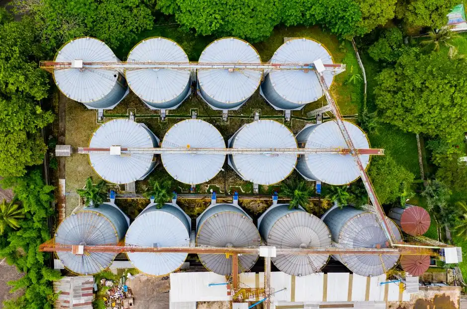
A lamella clarifier stacks inclined plates at 55–60° inside a rectangular or circular tank, multiplying the effective settling area inside a small footprint. Surface loading rates reach 20–40 m³/m²·h on a lamella versus 1–2 m³/m²·h for a conventional basin, which is why a 50 m³/h fab stream can be handled in a 6–8 m² footprint rather than 100+ m². Sludge recirculation drives floc density up and pushes the unit toward a solids-contact clarifier configuration, where a slurry blanket acts as a coarse filter for incoming floc.
The clarifier's strength is settleable, denser solids. After fluoride neutralization with calcium chloride or lime, precipitated CaF₂ and metals hydroxides (Cu(OH)₂, Ni(OH)₂) settle readily; after a hydroxide precipitation stage for copper and nickel, the sludge is dense enough that a lamella or circular clarifier captures it economically, with up to 30% lower coagulant consumption than conventional coagulation because the sludge blanket does some of the flocculation. For fabs whose wastewater is dominated by spent etch baths routed through a precipitation stage before primary clarification, a lamella unit is genuinely competitive.
The clarifier's weakness is colloidal carryover. CMP silica and ceria, fine photoresist fragments below ~20 µm, and emulsified IPA do not settle in a lamella — they pass through and load the downstream UF/RO train. Residence time is also tens of minutes versus minutes for a DAF contact zone, so a clarifier damps a hydraulic swing but cannot respond fast to a CMP slurry dump event. Where the influent TSS is already low, where the dominant load is precipitated metals sludge rather than CMP, and where the fab wants to minimize polymer carryover, a HydropureWater high-efficiency sedimentation tank (lamella clarifier) remains a defensible 2026 choice. The detailed trade-offs, including local reuse cases in Texas fabs, are in the Plano semiconductor DAF vs clarifier guide and the Marshall TX semiconductor DAF vs clarifier guide.
DAF vs clarifier for fab wastewater: the 2026 parameter comparison
The single most decision-grade artifact in any 2026 fab primary-clarifier selection is a parameter table that maps the equipment to fab duty, not to food or refinery duty. The table below uses DAF Corp published removal ranges, SigmaDAF model flow envelopes, lamella surface loading, and typical fab-side materials practice as of 2026.
| Parameter | Dissolved Air Flotation (DAF) | Lamella / Circular Sedimentation Clarifier |
|---|---|---|
| TSS removal (steady state) | 85–98% (92–98% circular FC; 85–90% rectangular RC) | 60–85% on fab streams; 85–95% on precipitated metals sludge only |
| FOG / photoresist skim removal | 85–98% on conditioned floc; primary FOG duty | 40–60% for free oils; poor on emulsified photoresist |
| Footprint per m³/h | ~0.2–0.5 m² per m³/h (compact skid) to ~0.6 m² (rectangular) | ~0.3–0.6 m² per m³/h (lamella); ~1.5–2.5 m² (circular conventional) |
| Hydraulic tolerance to load swings | Minutes-scale response; handles 2–3× design TSS spikes | Tens of minutes; damps swings but slow recovery |
| Chemical demand (coag + floc) | Higher; coag + pH adjust + polymer typical; jar-test required to protect UF | Lower; often coag + minor floc; up to 30% coag savings versus conventional coagulation |
| Materials of construction | 304SS standard; 316SS or polypropylene (PPL) for HF / strong acid / strong alkali | 304SS or rubber-lined carbon steel; 316SS / PPL for HF exposure |
| Influent TSS ceiling (design) | Up to ~2,000–5,000 mg/L with chemical conditioning | Up to ~500–1,000 mg/L without sludge recirculation; higher with solids-contact |
| Downstream fit for UF/RO/EDI | Strong — protects membranes from colloidal carryover; reuse-ready | Conditional — fine for reuse after metals precipitation; weak for CMP / photoresist |
| CAPEX band (qualitative) | Higher; lower footprint and tankage cost | Lower; larger footprint and tankage cost |
| OPEX band (qualitative) | Higher chemical; lower sludge handling per m³ | Lower chemical; higher sludge volume and disposal |
Flow-envelope reference: DAF Corp covers 48–11,000 GPM (0.7–1,250 m³/h), SigmaDAF Compact DAF covers single-skid up to 66 GPM (15 m³/h) with modular two-skid above, and the HydropureWater DAF range covers 4–300 m³/h across 13 models. Lamella units on fab duty typically run 10–200 m³/h per train in 2026 specifications.
Which fabs should pick DAF in 2026 — and which should still pick a clarifier
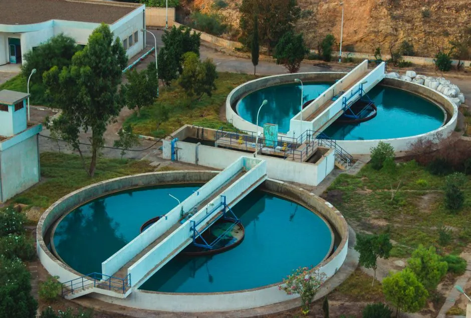
Logic microprocessor and chipset fabs — 300 mm and 200 mm lines running copper or cobalt damascene, advanced node photoresist stacks, and aggressive reuse targets — should default to DAF. The combination of colloidal CMP slurry, photoresist skimmings, and the need to protect downstream UF/RO from fouling is decisive. A rectangular or cross-flow DAF such as the HydropureWater dissolved air flotation system sized to peak hourly flow (not average) is the right answer; the Korean NRF study summarized in the Korean NRF study on material-specific UF/RO fouling in semiconductor fabs shows that primary-stage colloidal carryover is the leading root cause of membrane fouling in fab reuse loops.
NOR flash and memory fabs typically run on smaller, more variable flows than logic fabs, and a single-skid compact DAF up to 66 GPM (15 m³/h) covers most individual fabs or tool-cluster waste streams. Above that, scale to a modular two-skid or rectangular cross-flow unit. Fabs that already have a precipitation stage for HF neutralization can route the fluoride sludge through a HydropureWater high-efficiency sedimentation tank (lamella clarifier) to bulk-settle CaF₂, then send the overflow to a DAF for colloidal polishing — this hybrid configuration is increasingly common in 2026 retrofits.
Pick a clarifier as the primary stage when the dominant load is precipitated metals sludge, when polymer residuals are a concern for downstream reuse, when the plant already has gravity-settling infrastructure, or when the new fab train is a polish on an existing clarifier. Pick a hybrid (lamella primary + DAF polish) for any 2026 retrofit where the fab is moving from discharge-only to high-reuse and the existing basin can be repurposed. Upstream chemical conditioning in every case is best handled on a HydropureWater automatic chemical dosing system with streaming-current control, since the alternative is manual dosing and eventual membrane damage. For broader process design economics, the microelectronics wastewater engineering solution with 2026 ZLD cost breakdown is the relevant reference.
Sizing, materials, and integration notes for 2026 fab installations
Jar testing is not a step to skip. DAF Corp's own engineering guidance (2026) states that "considerable study and supporting information must be analyzed before choosing the best solution," and a comprehensive wastewater study is an up-front cost that minimizes future operating cost. For fab duty, the jar test matrix must include the actual CMP slurry (not a silica simulant), the photoresist chemistry in use, and a fluoride-spike to verify floc behavior at HF neutralization pH.
Materials selection is dictated by HF, TMAH, and strong oxidizer exposure. 304SS is acceptable for general fab streams; 316SS is required where chloride from HCl-bearing waste exceeds ~200 mg/L or where nitric acid is present; polypropylene (PPL) or PVDF linings are required wherever HF exceeds 100 mg/L or where TMAH is concentrated above 1%. DAF contact zones, saturation tanks, and chemical dosing skids should all be specified to the same materials envelope; mismatched wetted parts are a frequent source of 2025–2026 fab retrofit rework.
Integration is what makes the primary stage actually pay back. The chemical conditioning skid (coag + pH + polymer) sits upstream, sized to the DAF recycle ratio of 20–50% — for a 100 m³/h forward flow, expect 20–50 m³/h of pressurized recycle and a saturation pump sized accordingly. The DAF effluent hands off to a HydropureWater UF system for colloidal and emulsified oil polishing, then to a HydropureWater RO system for the bulk of the reuse water, with EDI or mixed-bed polish on critical UPW makeup streams. The primary clarifier is the first membrane-protection device in that train; sizing it for steady-state, not average, is the single biggest lever on membrane replacement frequency.
Frequently Asked Questions
Is DAF or a clarifier the right primary stage for meeting 40 CFR Part 433 metals and TSS limits in a fab?
For most microprocessor, chipset, and NOR flash fabs, DAF plus chemical conditioning is the default primary stage for 40 CFR Part 433 (Metal Finishing) compliance, because the colloidal load from CMP and photoresist cannot be settled economically. A lamella or circular clarifier alone is typically insufficient when the fab has aggressive reuse targets feeding UF/RO, though it is a defensible choice after a fluoride and metals precipitation stage where the load is already converted to settleable solids.
How does colloidal CMP slurry behave in a sedimentation clarifier versus a DAF?
Colloidal CMP slurry in the 30–200 nm range does not settle under gravity in any practical residence time, so a lamella or circular clarifier passes it through and loads the downstream UF train. DAF with polymer-conditioned floc and 30–50 µm micro-bubbles captures 85–98% of the colloidal load, which is why hybrid lamella + DAF is now common in 2026 fab retrofits that must hit high-reuse targets.
What footprint can a brownfield fab expect from a single-skid compact DAF versus a rectangular or lamella train?
A single-skid compact DAF handles flows up to 66 GPM (15 m³/h) in roughly 6–10 m² of floor area, including chemical conditioning, making it a strong fit for brownfield fabs with constrained headroom. Above 66 GPM, modular two-skid or rectangular DAF trains at ~0.5–0.6 m² per m³/h still beat lamella trains at ~0.6–1.5 m² per m³/h, and far beat conventional circular clarifiers at 1.5–2.5 m² per m³/h.
Do NOR flash fabs and logic microprocessor fabs pick the same primary clarifier?
They usually pick the same technology family (DAF) but different geometries. NOR flash and memory fabs on smaller, more variable flows are well served by a single-skid compact DAF up to 66 GPM. Logic microprocessor and chipset fabs with copper damascene, higher CMP load, and larger forward flow benefit from rectangular or cross-flow DAF units scaled to peak hourly flow, with chemical conditioning sized to the recycle ratio.
What materials of construction are required when HF is present in the fab wastewater?
316SS is the minimum acceptable material where HF is present at low to moderate concentrations and where chloride from HCl-bearing waste is significant. Polypropylene (PPL) or PVDF linings are required wherever HF exceeds ~100 mg/L or where TMAH is concentrated above 1%, and the same envelope must be applied to DAF contact zones, saturation tanks, and the chemical dosing skid — not just the clarifier vessel.