
Why Semiconductor Wastewater in Plano Is a Different Selection Problem
A Plano semiconductor fab runs four chemically distinct streams that converge in an equalization tank ahead of primary clarification. A CMP slurry waste carries fumed silica (~2.2 g/cm³) laden with Cu and Ta at 200–1,500 mg/L TSS. An etch waste delivers HF, TMAH, and NH₄OH at pH 2–4 upstream of neutralization. A photolith stream contributes photoresist, IPA, and NMP at densities near 1.0 g/cm³ — effectively buoyant in water. A solvent/HDI rinse adds trace hydrocarbons. The result: a blended feed in which 30–60% of the particulate load is in the 0.8–1.2 g/cm³ density window where Stokes' Law settling underperforms (HydropureWater field data, 2026). The North Texas Municipal Water District (NTMWD) treatment plants and the City of Plano's industrial pretreatment ordinance adopt 40 CFR Part 468 semiconductor limits by reference, and any direct discharge requires a TCEQ-administered TPDES permit. The IWC 25-75 paper "Exploring a semiconductor reclaim wastewater treatment plant operational optimization" (S2, ESWP, 2025) documents that fab-side operational tuning is part of the decision, because reclaim systems are sensitive to upstream equalization variability during tool ramp-down.
DAF and Clarifier: How Each Mechanism Actually Behaves on Fab Water
A dissolved air flotation system saturates a side-stream recycle at 5–7 bar, then releases it through needle valves to generate 30–50 µm microbubbles (per S4 SigmaDAF/Clearwater spec, 2026-04). Those bubbles attach to chemically flocculated particles and lift them to a paddle-skimmed surface, while heavier settled solids are augered from the bottom cone. The standard 304SS vessel ships in 13 models covering 4–300 m³/h, with 316SS and polypropylene available for fluoride service. Hydraulic residence time is 20–40 minutes, which is forgiving of fab surge flows during tool ramp-down.
A high-efficiency lamella clarifier uses 60° inclined plates to multiply the effective settling footprint at surface loadings of 20–40 m/h, with sludge recirculation sustaining a floc blanket for turbidity polishing. HRT is typically 1.5–3 hours. The hard mechanical limit is the settling velocity cutoff: particles below roughly 0.2 m/h are not captured regardless of plate area — which is why lamellas struggle with colloidal CMP silica and floating photoresist. Both units can use PLC-controlled polymer dosing skids (see the automatic chemical dosing system) to tune floc strength, but the underlying physics — gravity vs microbubble attachment — sets the performance envelope.
Stream-by-Stream: Which Technology Wins for Each Fab Waste Type
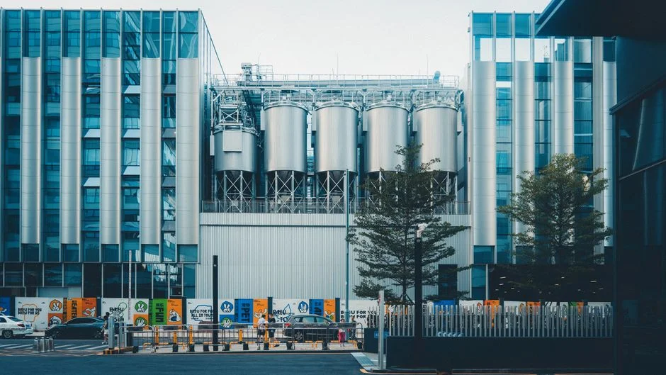
Mapping each fab stream to a unit operation avoids the trap of specifying one clarifier for "semiconductor wastewater" as if it were a single matrix. The table below summarizes the recommendation; the rationale follows.
| Fab Stream | Key Contaminants | Particle Density | Primary Recommendation | Secondary / Polishing |
|---|---|---|---|---|
| CMP slurry waste | Fumed silica, Cu, Ta, surfactants | ~2.2 g/cm³ (silica), but gel-like flocs | DAF (after polymer flocculation) | Lamella polishing if Cu load is low |
| Photoresist + IPA rinse | Photoresist (~1.0 g/cm³), IPA, NMP | Near 1.0 g/cm³ — buoyant | DAF (with vented skimmer hood for VOC) | Not applicable — lamella fouled |
| TMAH + fluoride etch (post-neutralization) | Metal hydroxides, CaF₂, high TDS | ~2.5–3.5 g/cm³ | Lamella clarifier | DAF not effective at high TDS |
| Heavy-metal precipitation (Cu/Ni/W) | Metal hydroxide floc | ~2.5–3.0 g/cm³ | Lamella clarifier | DAF polish before IX/RO |
| Mixed equalization (all streams) | Variable — TSS 200–800 mg/L, Cu, F | Mixed | DAF (15–25 pp higher TSS removal than lamella at same coagulant dose, per IWC 25-75 pilot data, S2, 2025) | Lamella polish then RO/UPW |
The CMP and photolith rows represent the primary argument for DAF. CMP silica forms gel-like flocs that do not settle cleanly even at high polymer dose, and photoresist physically fouls lamella plates within hours of operation. The IWC 25-75 paper (S2) reports that on a blended reclaim feed, DAF outperformed a parallel lamella train by 15–25 percentage points on TSS at matched coagulant dose — a gap significant enough to change downstream RO membrane loading.
The 40 CFR Part 468 Compliance Frame for Plano Fabs
40 CFR Part 468 sets the federal effluent limits that bind every U.S. semiconductor fab. Subcategory C (semiconductor) carries daily maximum and monthly average limits for copper, fluoride, TMAH, oil & grease, TSS, and pH. The daily maximum for copper is 1.6 mg/L and the monthly average is 0.80 mg/L; the fluoride daily max is 32 mg/L with a 16 mg/L monthly average (per 40 CFR §468.42, current as of 2026-05). Primary clarification alone rarely meets the Cu limit — the realistic job of a DAF or lamella is to drop Cu and TSS low enough that the downstream ion exchange or RO polishing step can finish the job without premature exhaustion. In Texas, TCEQ administers the TPDES permit for any direct discharge, and for industrial pretreatment to a POTW the controlling document is the local sewer use ordinance, which typically adopts 40 CFR 468 limits by reference. Plano fabs discharging to NTMWD systems should have the EHS team verify the current local limits before locking the equipment specification.
DAF vs Lamella Clarifier: 2026 Parameter Comparison for Plano Fabs
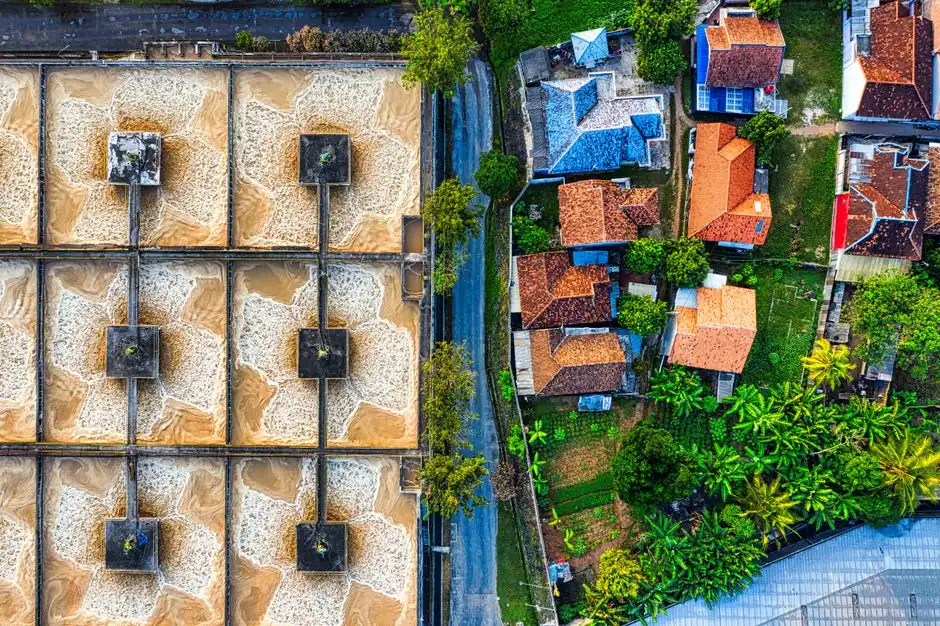
Engineers can use the following comparison table to evaluate equipment choices based on S4 SigmaDAF/Clearwater specifications (2026-04) and HydropureWater lamella data.
| Parameter | DAF (HydropureWater / SigmaDAF-class) | Lamella Clarifier (high-efficiency) |
|---|---|---|
| TSS removal (blended fab feed) | 80–95% | 55–75% |
| FOG / oil removal | 85–95% | 30–50% (limited) |
| Footprint (m² per m³/h) | ~0.3–0.5 | ~0.15–0.25 |
| Hydraulic residence time | 20–40 min | 1.5–3 h |
| CAPEX (30 m³/h unit, 2026 budgetary) | USD 60K–110K (304SS); 90K–150K (316SS) | USD 25K–70K (304SS); 45K–100K (316SS or PP) |
| OPEX (polymer + saturator air + sludge) | 10–20% higher than lamella | Lower polymer demand, no saturator |
| Chemical conditioning intensity | Coagulant + flocculant both required | Coagulant only typical; polymer optional |
| UPW-reclaim compatibility | Better — lower TSS load on RO/IX | Adequate as polish, weaker as primary |
| Surge flow tolerance | High (short HRT) | Low — floc blanket sensitive to hydraulic shock |
| HF/fluoride service | 316SS or PP required | 316SS or PP required |
Material of construction is the single biggest CAPEX swing factor. For HF-bearing streams, 316SS or polypropylene construction is mandatory — carbon steel is a non-starter for fab service regardless of which technology is selected.
When a Lamella Clarifier Beats DAF in a Fab — and When It Doesn't
Lamella is the correct primary when the feed is dominated by settled metal hydroxide floc from a neutralized etch stream, when no oils or photoresist are present, and when floor space is constrained. Lamella loses decisively when IPA or photoresist is present, when feed TSS is below ~200 mg/L with low-density colloids, and when the flow is highly variable, because the floc blanket is sensitive to hydraulic shock. The IWC 25-75 case (S2) documents a hybrid layout that many fabs adopt: a lamella clarifier on the etch/neutralization line, a DAF on the photolith/CMP line, then equalization before the polish train. This configuration plays to each technology's strengths and avoids forcing either unit onto a stream where it will underperform.
Sizing, Vendor RFQ, and Pilot Testing Checklist
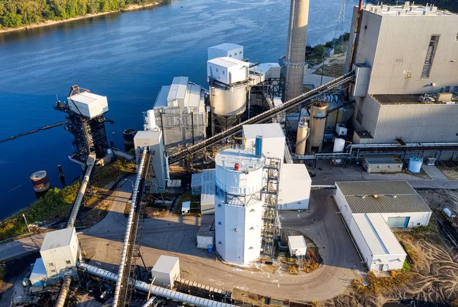
Converting the analysis into an action list follows a logical sequence. Step 1: pull the past 12 months of upstream equalization tank data — flow range, peak/avg ratio, TSS, FOG, Cu. Step 2: run a bench-scale jar test with the actual fab feed and 2–3 polymer types at 0.5–3 mg/L doses; record float vs settle behavior on each sample. Step 3: pilot a 1–5 m³/h unit on site for 4–6 weeks — the IWC 25-75 paper (S2) makes the case that pilot work on fab reclaim streams pays back in avoided full-scale rework. Step 4: issue the RFQ with at least 304SS and 316SS pricing, PLC control scope, and skid vs field-assembled preference. The dissolved air flotation system and the high-efficiency lamella clarifier both ship in skid form with 13 model sizes covering 4–300 m³/h, and a PLC-controlled polymer dosing skid integrates with either. Step 5: build the ROI case. DAF OPEX is typically 10–20% higher than lamella due to polymer and saturator compressed air, but the better TSS and Cu reduction lowers downstream IX/RO membrane replacement frequency. Engineers who want a broader spec baseline can also reference the DAF system specifications 2026 guide and, for TFT-LCD comparator fabs, the TFT-LCD wastewater discharge standards 2026 breakdown. For a ZLD-oriented downstream design, the silicon wafer ZLD engineering solution 2026 case study documents the hybrid path most Plano reclaim systems are now heading toward.
Frequently Asked Questions
Is DAF or a lamella clarifier the better primary for a Plano fab blending CMP, photoresist, and etch waste?
DAF. With CMP silica flocs, floating photoresist, and IPA in the blend, the feed is dominated by low-density material that a lamella cannot capture; DAF microbubbles attach and lift these particles reliably (per SigmaDAF equipment data, 2026-04). The IWC 25-75 paper (S2) reports 15–25 percentage points higher TSS removal for DAF over lamella at matched coagulant dose on a similar blended reclaim feed.
What 40 CFR Part 468 limits drive the primary clarifier
Frequently Asked Questions
Should a semiconductor fab use DAF or a clarifier for CMP wastewater?
For Chemical Mechanical Planarization (CMP) wastewater, a Dissolved Air Flotation (DAF) system is generally superior to a traditional gravity clarifier due to the low density and sub-micron size of silica slurry particles. DAF units utilize micro-bubbles to float these colloidal solids to the surface, achieving removal efficiencies of 90-98% for suspended solids, whereas gravity clarifiers often struggle with the slow settling rates of CMP particles without excessive chemical polymer dosing.
What is the difference between DAF and a lamella clarifier in semiconductor manufacturing?
The primary difference lies in the separation mechanism: DAF relies on buoyancy, using pressurized air to lift particles, while a lamella clarifier uses gravity settling across inclined plates to increase the effective surface area. In semiconductor applications, lamella clarifiers are preferred for high-density metal hydroxide precipitates, while DAF is optimized for oily emulsions, low-density silicas, and wastewater streams where footprint minimization is critical due to the high rise rates achievable in flotation cells.
Does a DAF system meet 40 CFR Part 468 effluent limits for copper and TMAH?
A DAF system alone is insufficient to meet 40 CFR Part 468 effluent guidelines for copper and Tetramethylammonium hydroxide (TMAH) because these contaminants are typically in dissolved ionic form. DAF is a physical separation process for suspended solids; therefore, it must be integrated into a broader treatment train that includes chemical precipitation for copper removal and advanced oxidation processes (AOP) or biological treatment for the degradation of TMAH to ensure compliance with federal discharge standards.
How much does a 50 m³/h DAF system cost for a semiconductor plant in 2026?
For a high-purity, industrial-grade 50 m³/h DAF system designed for semiconductor specifications, capital costs in 2026 typically range from $280,000 to $450,000. This pricing includes stainless steel construction, automated sludge scraping mechanisms, pressurized recycle pumps, and integrated control panels, but excludes installation, civil works, and peripheral chemical dosing skids, which can increase total project costs by an additional 30-50%.
Can a lamella clarifier handle photoresist and IPA wastewater from a fab?
A lamella clarifier is largely ineffective for treating photoresist and Isopropyl Alcohol (IPA) because these substances are typically dissolved or in stable colloidal suspension rather than settleable solids. Photoresist often requires pH adjustment and coagulation to form flocs, while IPA remains fully soluble in water; consequently, these streams require specialized treatment such as membrane filtration, dissolved air flotation with specific flocculants, or thermal oxidation to effectively manage organic loading before discharge.