The Three-Layer Rule That Governs Every Snoqualmie Fab Discharge
Three overlapping rules govern every semiconductor discharge from a Snoqualmie-area fab to a King County sewer — and the strictest of the three is the only one that matters at the discharge point. The federal anchor is the EPA Industrial Pretreatment Program at 40 CFR Part 403, which establishes the categorical framework at 40 CFR Parts 405–471 (per EPA 40 CFR 403.6) and sets the general duty to prevent pass-through, interference, and sludge contamination. Layered on top is 40 CFR Part 413, the semiconductor categorical standard with its PSES (existing sources) and PSNS (new sources) effluent ceilings. Layered above both is King County's Sewer Use Ordinance, enforced by the King County Industrial Waste Program (KCIW) under King County Code 28.84.060, which can and does impose limits tighter than the categorical floor when the receiving POTW's headworks, digesters, or receiving stream require it.
For Snoqualmie-area fabs in particular, the receiving POTW is one of two large King County plants — West Point in Seattle or the South Treatment Plant in Renton — both of which accept industrial flow from the Sammamish Plateau and the South Fork Snoqualmie interceptor service area. A categorical floor that passes a fab at one POTW can still fail at another, because 2023 openRxiv research on US sewer connectivity found that downstream POTW capacity is highly uneven across the country (openRxiv 2023-05). The categorical floor is rarely the binding ceiling; King County's local limits and the headworks tolerance almost always undercut it. The EPA 40 CFR Part 403 framework is the legal mechanism that makes compliance with those tighter local ceilings enforceable through KCIW-issued permits.
Any "Categorical Industrial User" under 40 CFR 403.3(j) — which includes semiconductor fabs subject to 40 CFR Part 413 — must obtain a full KCIW discharge permit regardless of discharge volume. Non-significant users discharging less than 5,000 gpd still have to comply with King County's instantaneous limits, but they avoid the full IPP permit and the monthly DMR cycle. For a parallel federal categorical walkthrough on a different industrial sector, the 40 CFR 414 chemical plant pretreatment guide covers the same three-layer logic on the organic chemicals side.
What King County Actually Enforces at the Snoqualmie Receiving POTW
Translating the federal framework into a wall-pinned engineering reference, the binding limits a Snoqualmie-area fab has to hit at the discharge point are set by KCIW's local-limits document PUT 8-13-2-PR, the prohibited discharge standards at 40 CFR 403.5, and King County Code 28.84.060. The parameter set below is the working envelope for a Categorical Industrial User fab; non-significant users below 5,000 gpd comply only with the instantaneous columns.
| Parameter | King County Limit | Basis / Notes |
|---|---|---|
| pH, instantaneous | 5.0 minimum; 12.0 maximum | Any grab sample; per KCC 28.84.060 |
| pH, daily minimum | 5.5 sustained ≥15 minutes | Also violated on four consecutive sub-5.5 grabs |
| Nonpolar FOG | 100 mg/L | Daily average; separator plan KCIW-approved |
| Settleable solids | 0.5 mL/L | Imhoff cone, 1 hour |
| Temperature at discharge | ≤150°F (65°C) | KCC 28.84.060 |
| Temperature at headworks | ≤104°F (40°C) | Treatment plant influent |
| Total metals (Cu, Ni, Cr, Pb, Ag) | mg/L daily-max + lb/day mass allocation | One standard deviation of plant avg flow |
| Soluble sulfide | 0.1 mg/L screening | Case-by-case restriction |
| Flammable / explosive | Closed-cup ≥140°F; ≤10% LEL single reading, ≤5% LEL on two consecutive | 40 CFR 261.21 methods; KCC |
Three engineering consequences follow from this table. First, King County's mass-based metals limits are calculated in lb/day at one standard deviation of the receiving plant's average flow — this is a design-day calculation, not an annual-average calculation, and it is the number the train has to hit on the worst shift, not on a 12-month rolling mean. Second, the 150°F discharge cap and the 104°F headworks cap force any elevated-temperature stream to be tempered before the sewer, and any process that wants to feed a heat exchanger upstream of discharge needs that exchanger sized against the 65°C ceiling, not the 40°C ceiling. Third, the categorical semiconductor user always needs a full KCIW permit — categorical status is the trigger, not discharge volume (per KCIW categorical-discharger framework on the King County Industrial Waste wastewater discharge limits and regulations page).
The Fab Stream Map: Fluoride, Metals, TMAH, and Utility Drains

Every pretreatment decision at a Snoqualmie fab traces back to which drain is being treated and what the binding parameter is for that drain. The four-stream map below is the one that drives segregation on the P&ID, and the P&ID decision is the one that is almost impossible to retrofit cheaply on a brownfield.
| Drain Family | Key Pollutants | Typical Concentration | Binding Parameter |
|---|---|---|---|
| Wet-etch / post-etch cleaning | HF, NH₄F, strong/weak acids | 50–500 mg/L as F⁻ | Fluoride (KCIW <15 mg/L target) |
| CMP slurry / filter backwash | Cu, Ni, Co, Cr, Pb, Ag; fine oxides | ≤1–3 mg/L individual; ≤5 mg/L combined | Total metals; lb/day mass allocation |
| Photoresist developer | TMAH, isopropyl additives | 100–200 mg/L TMAH site-dependent | TMAH + NH₃-N ~50 mg/L after biodegradation |
| Utility floor drains | Lubricants, oil, lint, hair | O&G ≤10–50 mg/L | Screen protection; FOG 100 mg/L cap |
The developer stream is the one that breaks simple "combine everything" train designs. TMAH biodegrades fastest outside the fluoride precipitation pH window, and its ammonia byproduct drives an NH₃-N ceiling near 50 mg/L — a separate number on the KCIW permit from the TMAH number itself. Combining the developer drain with the etch drain forces the operator to dose toward a compromise pH and accept higher reagent use; keeping it segregated lets the developer run on its own temperature/pH schedule and lets the etch and metals streams run on the windows where CaF₂ and metal hydroxides actually precipitate.
Stage 1 — Source Segregation and Headworks Protection
Source segregation is a piping decision made at fab design time — fluoride, CMP/TMAH, and utility-floor streams stay on separate headers from the wet bench back to the pretreatment building, and the P&ID shows it long before any chemistry skid is selected. A brownfield retrofit that has to break combined headers is one of the most expensive capex lines on the project, so this scope item has to land in the front-end engineering package, not in construction change orders.
On the headworks, a rotary mechanical bar screen at 2–6 mm bar spacing, sized to design-day peak flow with auto-cleaning and brush discharge, is the highest-ROI line item on the train. The frame for it is low-capex / high-opex-protection: particulates, hair, and lint from utility-floor drains are the leading cause of dosing-pump diaphragm failure and DAF recycle eductor clogging, and a screen that costs a fraction of one dosing-pump rebuild keeps the rest of the train online. Pull design-day, not average-day, loads when sizing this screen — batch discharges from wet-etch tools and post-CMP cleaning can swing instantaneous fluoride and solids by 3–5× over the daily average (HydropureWater field data, 2026).
Stage 2 — pH Control and Calcium-Driven Fluoride Precipitation
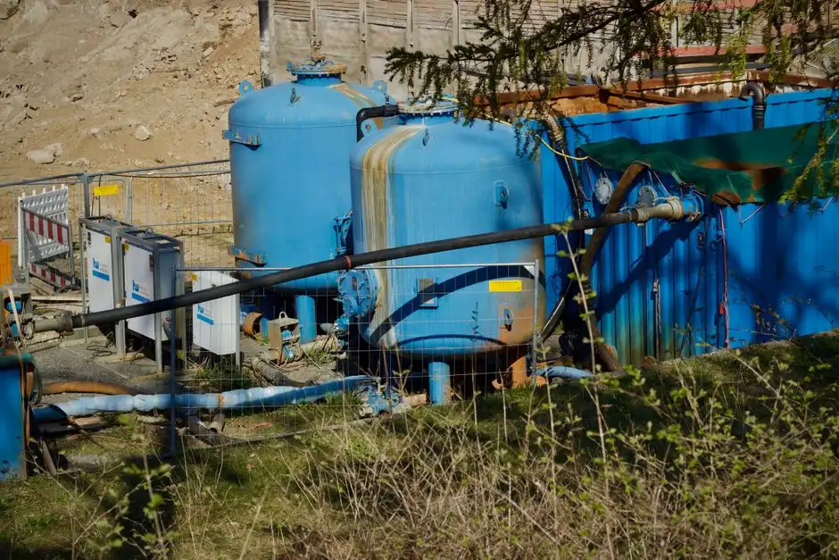
Calcium-driven precipitation is the workhorse of fab fluoride removal, and the reason is thermodynamic. CaCl₂ (or lime, Ca(OH)₂) dosed into the fluoride stream at pH 6–8 drives the reaction F⁻ + Ca²⁺ → CaF₂↓, and the Ksp of CaF₂ is approximately 3.9 × 10⁻¹¹ — a small enough solubility product that single-digit mg/L fluoride effluent is thermodynamically reachable in a well-mixed, well-controlled reactor. The metal-bearing stream goes to pH 9–10.5 with NaOH or lime, where Cu, Ni, Co, Cr(III), Pb, and Ag all reach their minimum solubilities as hydroxides. The two streams are then recombined into a single equalization basin ahead of Stage 3.
Equipment-level execution is where most fab pretreatment trains actually win or lose. A PLC-controlled chemical dosing skid with redundant pH probes and a fluoride ion-selective electrode (ISE) on automatic two-point calibration holds reagent addition within ±5% of setpoint, which is the difference between meeting a 15 mg/L fluoride cap and oscillating around it. Specify at least 10:1 turndown on the metering pumps, and require the skid to accept both 4–20 mA flow-pacing and pH/ISE feedback so the same skid can track a rinse-water spike without overdosing caustic. Size the skid on peak fluoride and metal mass load in kg/day, not on average flow, because peak-day loads are what the dose-control loop actually has to hold.
The long-term reliability failure mode on this stage is the pH probe itself, not the chemistry. Probe drift, coating, and reference-junction fouling are the most common reasons a Stage 2 skid starts to pass a higher fluoride number than the setpoint would predict; this has to be carried as a maintenance scope item with a defined calibration cadence, not buried in a footnote.
Stage 3 — DAF vs Lamella: The Real Decision for a Snoqualmie Fab
The solids/liquid separation decision in fab pretreatment is driven by three numbers an engineer already has: peak flow (m³/h), influent TSS after coagulation, and available bay footprint. The head-to-head below is the basis for picking the right device, not a default to whichever the EPC is most comfortable with.
| Selection Driver | DAF | Lamella Clarifier |
|---|---|---|
| Flow range | 4–300 m³/h | Moderate flows |
| Hydraulic / surface loading | 4–25 m/h HLR | 20–40 m/h SLR |
| Best-fit stream | High float loading; oily; fluoride-rich | Denser floc; moderate TSS |
| Footprint | Larger bay; high float scraping | Compact; high-rate plates |
| Overflow TSS (well-tuned upstream) | Below 30–60 mg/L SUO range | Below 30–60 mg/L SUO range |
Both devices routinely deliver overflow TSS below the 30–60 mg/L SUO range when the upstream Stage 2 chemistry is correct — neither device buys compliance on its own. The DAF system is the right answer for high-flow, low-density, oily, or fluoride-rich streams with high float loading; the high-efficiency lamella clarifier wins when flows are moderate, solids are denser, and the building bay is tight. For chromium-bearing streams (third-generation fab work), a dedicated Cr(VI) reduction and precipitation step must be added upstream of whichever Stage 3 device is selected — that is a scope item, not a footnote. A useful side-by-side treatment of this trade space on a different industrial wastewater is the DAF vs clarifier factory guide.
Stage 4 — Polishing for Compliance and 2026 Reuse Targets
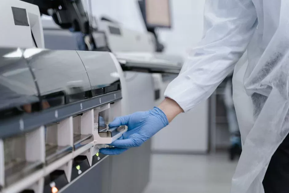
Polishing is what separates a compliance-only train from a water-stewardship train, and the same four-stage train that hits the KCIW limits also enables reuse. The decision rule is short: pick ion exchange when the polishing duty is primarily trace metals and hardness, throughput is ≤50 m³/h, and the operator is comfortable with regeneration cycles. Pick RO when the fab has a documented reuse target of ≥50% of pretreatment effluent and an industrial-grade reject-stream management plan.
An industrial RO polishing system delivers 75–95% recovery per pass and drops TDS plus residual fluoride to levels suitable for non-critical rinsing, cooling-tower makeup, or scrubber feed. RO permeate that is not reused is sewered well below any applicable limit, so there is no compliance penalty for sending clean water to the POTW. For facilities pushing toward zero-liquid-discharge, the same front-end chemistry feeds a downstream evaporator/crystallizer — the front-end chemistry is what makes ZLD economics work, not the back-end evaporator. For chromium-bearing streams, a dedicated Cr(VI) reduction step is required upstream of IX/RO; that is a scope item on the P&ID, not a footnote.
Sludge Handling, King County Mass Loading, and the Permit Cycle
The solids removed in Stage 3 — CaF₂, metal hydroxides, and CMP residue — report as a thickened sludge typically at 1–4% dry solids, and a plate and frame filter press sized from 1 m² (pilot) to 500 m² (full fab, multi-press line) dewateres that sludge to a 25–35% dry-solids cake for off-site disposal. Filtrate returns to the head of the train and is not lost to the mass balance. The cost swing on the back end is disposal routing: if the upstream chemistry produces a sludge that retains pollutants through EPA's TCLP, the cake can be disposed of as non-hazardous waste at a fraction of hazardous-waste rates. Polymer flocs often fail TCLP and re-leach under dewatering pressure; one-step, automated, bentonite-based separating chemistries are engineered to retain pollutants through TCLP and produce an easily dewatered cake.
King County's mass-based metals limit is set in lb/day at one standard deviation of average plant flow, per the KCIW mass allocation procedure (KCIW local-limits document PUT 8-13-2-PR). A worked calculation for a Snoqualmie fab with combined metals of 5 mg/L on a design-day flow of 200 m³/day yields roughly 2.2 lb/day combined metals load — that is the number the train has to demonstrate it can hold under design-day, not annual-average, conditions, and it is the number an IPP permit is written against. A summary of the permit and solids cycle is below.
| Item | Number / Specification | Source / Basis |
|---|---|---|
| Sludge thickening | 1–4% dry solids | Stage 3 underflow |
| Cake dryness (filter press) | 25–35% dry solids | Plate and frame, 1–500 m² |
| King County mass loading method | lb/day at 1σ of plant avg flow | PUT 8-13-2-PR |
| IPP permit term | 5 years | KCIW |
| DMR cadence | Monthly to KCIW | 40 CFR 403.12 |
| POTW inspection cadence | Annual baseline; more if SNC | KCIW ERP |
| Slug-control plan | Required for CIUs | 40 CFR 403.8(f)(2) |
| Haul vs sewer cost (2025-09) | Liquid hazardous waste 5–10× per m³ | Industry benchmark, 2025-09 |
The IPP permit cycle is what turns equipment into a compliance program. Monthly self-reported Discharge Monitoring Reports go to KCIW, annual baseline POTW inspections cover hardware plus paperwork, and every piece of equipment on the train has to be backed by an SOP and a calibration record. Significant Non-Compliance facilities see more frequent inspections and stricter enforcement-response triggers under the KCIW Enforcement Response Plan. The 2025-09 industry benchmark that hauling liquid hazardous waste off-site runs 5–10× the cost per cubic meter of sewer discharge is the number that closes the back-end economics — the same train that achieves compliance also closes the disposal cost line.
Frequently Asked Questions
What is the binding sewer limit a Snoqualmie semiconductor fab has to hit in 2026?
King County's local Sewer Use Ordinance, enforced through KCIW, is the binding ceiling — stricter than the 40 CFR Part 413 categorical floor. Practically, that means fluoride below 15 mg/L, individual heavy metals at 1–3 mg/L, combined metals ≤5 mg/L, and TMAH/NH₃-N to roughly 50 mg/L on the developer stream (per KCIW PUT 8-13-2-PR).
What does a four-stage pretreatment train for a Snoqualmie fab look like?
Stage 1 segregates fluoride, CMP/TMAH, and utility-floor streams; Stage 2 doses CaCl₂ into the fluoride stream at pH 6–8 to precipitate CaF₂ (Ksp ≈ 3.9 × 10⁻¹¹) and NaOH or lime into the metal stream at pH 9–10.5; Stage 3 uses a DAF or lamella clarifier; Stage 4 polishes with ion exchange or RO at 75–95% recovery for trace metals, hardness, and reuse.
How is compliance documented to KCIW once the train is running?
The KCIW-issued IPP permit runs 5 years and requires monthly Discharge Monitoring Reports, continuous pH and flow monitoring, periodic fluoride and total-metals analyses, annual baseline POTW inspections, a slug-control plan, and SOP plus calibration records for every piece of equipment on the train (per 40 CFR 403.12 and the KCIW Enforcement Response Plan).
Can the same train deliver water for on-site reuse as well as compliance?
Yes. After precipitation, DAF or lamella clarification, and polishing through ion exchange or an industrial RO system operating at 75–95% recovery per pass, the effluent is suitable for non-critical rinsing, cooling-tower makeup, or scrubber feed. RO permeate that is not reused is sewered well below any applicable limit, so reuse and compliance are complementary, not competing.
How is the King County metals mass-loading calculation actually done?
King County mass-based metals limits are set in lb/day at one standard deviation of the receiving plant's average flow, per the KCIW mass allocation procedure. For a Snoqualmie fab, the design-day combined metals load (mg/L × design-day flow) is calculated against that ceiling, and the train is sized to hold under design-day, not annual-average, conditions — that is the number an IPP permit is written against.