CASS Sizing Decision Framework: Flow, Load & Standard First
CASS process sizing for 2,000–100,000 m³/d plants utilizes a Main Aeration zone comprising ~85% of the basin volume, Secondary Aeration at ~10%, and a cycle structure of 4–8 hours to consistently meet GB 18918-2002 Grade 1A standards (TN ≤15 mg/L, TP ≤0.5 mg/L). Engineers must define the design flow and influent profile to ensure the cyclic activated sludge system design is appropriate for the site constraints. Accurate hydraulic modeling at the pre-design stage prevents operational bottlenecks and ensures that the biological processes remain robust against seasonal fluctuations.
- Design Flow: Establish the Average Daily Flow (ADF) and apply a Peak Hourly Factor (PHF) typically ranging from 1.5 to 2.5. Per Liu et al. (2021), an equalization volume of at least 15% of ADF is mandatory to prevent toxic shock and hydraulic surges. Incorporating this buffer allows for stable biological respiration rates during storm events or peak hourly spikes.
- Effluent Compliance: Achieving Grade 1A requires balancing the Solids Retention Time (SRT) and the duration of the react phase to facilitate simultaneous nitrification denitrification (SND). Target effluent limits are BOD ≤10 mg/L, SS ≤10 mg/L, and NH3-N ≤5 mg/L. Precise control of the dissolved oxygen (DO) setpoints is required to maintain these limits throughout the year.
- Influent Characterization: Typical municipal influent ranges include BOD 150–300 mg/L and a COD/BOD ratio of 1.8–2.2. If TKN exceeds 50 mg/L or TP exceeds 8 mg/L, additional pre-treatment or carbon dosing strategies must be integrated into the sizing model to ensure the microbial population remains active.
- Capacity Thresholds: For flows below 2,000 m³/d, consider a containerized underground package plant. For projects between 2,000 and 100,000 m³/d, basin-based CASS is the standard, while projects exceeding 100,000 m³/d often require parallel process trains to maintain operational redundancy and allow for maintenance without full system shutdown.
- Geometric Constraints: Optimal basin depth is 4–5 m. Depths below 1.5 m or exceeding 6 m can compromise decanter clearance and hydraulic efficiency. Engineering teams must also account for the freeboard requirements to prevent splashing and aerosol transmission during high-intensity aeration cycles.
First-Principles Sizing Parameters: Loading Rates, F/M, HRT, SRT
The core sizing of a cyclic activated sludge system relies on the biological loading rates and retention times necessary to maintain stable biomass populations (HydropureWater field data, 2026). The following table provides the design ranges required for Grade 1A compliance as a baseline for modern municipal wastewater facility designs.
| Parameter | Design Range | Notes |
|---|---|---|
| F/M Ratio | 0.05–0.15 kg BOD/kg MLSS·d | Use 0.05–0.08 for nitrification-heavy duty |
| HRT (Total Cycle) | 8–18 hours | Calculated based on ADF and basin geometry |
| SRT | 15–30 days | 15d at 25°C; 30d at 10°C for nitrification |
| MLSS | 3,000–5,000 mg/L | Main Aeration zone concentration |
| Chemical P-Removal | 1.5–2.5 mol Me/mol P | Integrate automatic chemical dosing system |
| Sludge Production | 0.6–0.8 kg TSS/kg BOD | Process via plate & frame filter press |
Temperature correction is critical for nitrification kinetics, as the reaction rate follows a temperature coefficient θ = 1.072. When ambient temperatures drop to 10°C, the required react phase duration effectively doubles compared to operations at 20°C. To manage phosphorus removal to ≤0.5 mg/L, chemical precipitation via the dosing unit is recommended at the Secondary Aeration outlet to ensure optimal flocculation before the decant phase. Maintaining consistent sludge age through controlled wastage is also paramount to preventing biomass washout during high-flow winter conditions.
Cycle-Phase Time Allocation & Zone Volume Design
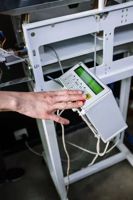
A standard 6-hour cycle allocates time based on the specific biological and hydraulic requirements of the system to ensure each phase contributes to the final effluent quality (per Liu et al., 2021). Efficient management of these cycles optimizes energy usage and ensures the chemical oxygen demand is fully oxidized.
- Cycle Breakdown: Fill (15% / 54 min), React (55% / 198 min), Settle (20% / 72 min), Decant (10% / 36 min). The Idle phase is often absorbed into the React phase to maximize biological uptake and reduce the total number of moving parts in the system.
- Zone Geometry: Main Aeration (85% volume) handles the bulk of organic degradation and SND. Secondary Aeration (10% volume) acts as a buffer for initial nitrification. The Selector/Anoxic zone (5% volume) is essential for filament control and phosphorus release, which significantly improves the settleability of the final sludge blanket.
- Decanter Sizing: The peak decant rate formula is (ADF × PHF) / (decant time × number of basins). For a 20,000 m³/d plant with two basins and a 0.6-hour decant time, the required capacity per basin is 33,333 m³/hr. Designers must verify that the decanter weir length is sufficient to avoid high-velocity surface draw, which could lead to carryover of suspended solids.
- Energy Optimization: Utilizing RRC (Reduced Rate Control) aeration during the React phase can reduce total plant energy consumption by 20–35% compared to continuous fine-bubble aeration. Smart sensors that monitor real-time ammonia levels allow for dynamic adjustment of blower speeds, directly impacting operational costs.
- Biofilm Integration: Adding an MBBR carrier fill ratio of 15–30% in the Main Aeration zone provides a nitrification lift, which is particularly effective during cold-weather operation or when retrofitting existing basin footprints for higher capacity. This hybrid approach adds a safety factor against biomass inhibition caused by industrial toxins or extreme pH shifts.
CASS vs. Continuous-Flow CAS vs. MBR vs. IFAS: 2026 Capacity Comparison
Selecting the optimal technology for a 20,000 m³/d project requires evaluating footprint, capital expenditure (CapEx), and operational expenditure (OpEx) indicators relative to standard activated sludge (CAS) baselines. Investors should prioritize life-cycle cost analysis to ensure long-term economic viability.
| Technology | Footprint Index | CapEx Index | OpEx Index |
|---|---|---|---|
| CAS | 1.0 | 1.0 | 1.0 |
| CASS | 0.65 | 0.95 | 0.85 |
| MBR | 0.40 | 1.50 | 1.20 |
| IFAS | 0.75 | 1.10 | 0.90 |
For detailed technical trade-offs, refer to MBR vs. CAS vs. IFAS detailed comparison. CASS offers a balance for mid-to-large scale municipal projects where the elimination of secondary clarifiers reduces the overall plant footprint and civil costs. While MBR alternatives for Grade 1A provide high effluent quality, they require higher energy input for membrane scouring and replacement cycles. When high-strength industrial influent is present, engineers may consider IFAS design parameters for high-strength industrial wastewater to manage variable loads within the same basin footprint. Choosing the correct technology requires matching the specific discharge permit needs with the available local technical support and maintenance capabilities.
Spec Sheet Template: What to Send Vendors for Accurate Quotation
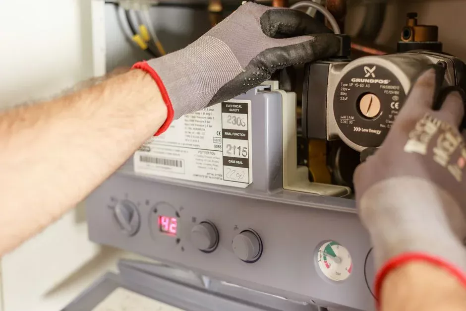
Providing standardized data points in your Request for Information (RFI) streamlines the procurement process and minimizes hidden costs.
- Influent Specs: ADF (m³/d), PHF, BOD/COD/TN/TP/SS concentrations, and temperature range (min/max).
- Effluent Requirements: Grade 1A limits (TN ≤15, TP ≤0.5, NH3-N ≤5, BOD ≤10, SS ≤10).
- Process Configuration: Number of basins, preferred cycle time, and decanter type (e.g., floating decanter vs. fixed-arm).
- Automation: PLC platform, SCADA integration requirements, and the number of DO/pH/ORP/MLSS sensors.
- Civil Work: Basin material (concrete/steel), depth constraints, and seismic design criteria.
- Sludge Management: Required waste sludge concentration and preferred dewatering technology (e.g., belt press, filter press).
- Guarantees: Performance bond requirements, specific power consumption (kWh/m³ treated), and maintenance intervals for mechanical components.
Frequently Asked Questions
What is the recommended cycle time for a CASS plant?
The standard cycle time is 4–8 hours. For Grade 1A compliance, a 6-hour cycle is typical: Fill (15%), React (55%), Settle (20%), and Decant (10%). Adjustments should be made based on temperature; lower temperatures require longer react phases for nitrification (per Liu et al., 2021). Operators should conduct pilot tests if the influent composition fluctuates significantly throughout the day.
How is the decanter capacity calculated for peak flows?
Decanter capacity is determined by the peak hourly flow (PHF) divided by the total decant time and the number of operational basins. For a 20,000 m³/d plant with a PHF of 2.0 and two basins, the design must handle 33,333 m³/hr per basin during the decant phase. Ensuring the decanter is sized for the absolute peak is vital for maintaining the integrity of the settle phase.
Is CASS suitable for retrofitting existing CAS plants?
CASS is highly effective for retrofitting by utilizing existing basin volumes through the installation of decanters, upgrading aeration systems to RRC, and implementing PLC-based cycle controls. For plants requiring higher nitrification capacity, adding an MBBR carrier fill ratio of 15–30% is a common strategy (HydropureWater field data, 2026). This approach maximizes the utility of existing infrastructure while meeting modern emission standards.
Related Equipment
- lamella clarifier for CAS/IFAS comparison — specifications, capacity range, and technical data
Further Reading
- CASS retrofit guide with carrier addition and RRC aeration