How Santa Clara Pretreatment Limits Bind Fab Discharge
Santa Clara pretreatment limits bind fab sewer discharge to the strictest local Sewer Use Ordinance at the receiving POTW, with segregated etch, CMP, developer, and utility trains. Federal 40 CFR 403 and 40 CFR 413 set the procedural floor and categorical minimums. Local fluoride, metals, ammonia, and oil-and-grease ceilings decide the equipment size.
Santa Clara pretreatment limits sit inside a three-layer stack. 40 CFR 403 builds the Industrial Pretreatment Program to stop pass-through and interference at the publicly owned treatment works, yet it carries no numeric pollutant ceilings. 40 CFR 413 sets semiconductor categorical effluent standards that act as a federal floor, not a site-specific permit. Per EPA 40 CFR 403.5(c), each POTW must write and enforce local limits that protect its headworks, digesters, and receiving waters.
For any fab project in Santa Clara, obtain the current SUO and IPP discharge permit from the POTW that serves the parcel. County flow goes to Palo Alto RWQCP, San Jose-Santa Clara RWF, or Sunnyvale WPCP, so design setpoints shift by address.
| Regulatory Layer | Function | Binding Status |
|---|---|---|
| 40 CFR 403 (IPP) | Prevents interference/pass-through | Procedural framework |
| 40 CFR 413 (Categorical) | Industry-wide effluent floor | Federal minimum |
| Local SUO | Site-specific pollutant ceilings | Binding limit (Strictest) |
What Limits Apply to a Semiconductor Fab in Santa Clara?
A semiconductor fab in Santa Clara must meet the numeric ceilings in the SUO of Palo Alto RWQCP, San Jose-Santa Clara RWF, or Sunnyvale WPCP—whichever collection system serves the site. Miss those thresholds and the facility enters Significant Non-Compliance with mandatory quarterly inspections. The table below summarizes the 2023-2024 published limits for key semiconductor contaminants.
Sunnyvale WPCP holds the county’s tightest fluoride ceiling at 10 mg/L. San Jose-Santa Clara RWF requires a formal slug control plan when fluoride exceeds 50 mg/L. Most plants we size for copper run toward the lower end of the local metal range because CMP spikes push grab samples hard.
| Parameter | Palo Alto RWQCP | San Jose-Santa Clara RWF | Sunnyvale WPCP |
|---|---|---|---|
| Fluoride (mg/L) | 15 | 25 | 10 |
| Copper (mg/L) | 1.5 | 2.0 | 1.0 |
| Nickel (mg/L) | 2.0 | 2.5 | 1.5 |
| Ammonia (NH₃-N) | 45 | 50 | 40 |
| Oil & Grease | 100 | 50 | 50 |
All three facilities mandate monthly Discharge Monitoring Reports and five-year permit renewals. Continuous fluoride ion-selective electrode monitoring on the effluent header keeps Santa Clara pretreatment limits under control around the clock, not only at grab-sample windows. Targeted chemistry on segregated streams makes those numbers achievable.
How Should a Santa Clara Fab Segregate Waste Streams?
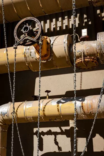
Santa Clara fabs should segregate wet-etch, CMP, developer, and utility drains at the source because mixed streams force a compromise pH that blocks efficient removal. Each drain carries a distinct chemical signature and needs its own treatment window. Blending those streams raises reagent use and can cut fluoride removal efficiency by 40-60% when pH drifts outside the 6-8 range.
| Stream Type | Primary Contaminants | Treatment Requirement |
|---|---|---|
| Wet-Etch/Cleaning | HF, NH₄F (50-500 mg/L F⁻) | CaCl₂ precipitation at pH 6-8 |
| CMP Slurry | Metals (Cu, Ni, Cr), oxides | Hydroxide precipitation at pH 9-10.5 |
| Developer Drains | TMAH (100-200 mg/L) | Separate nitrification/stripping |
| Utility Drains | O&G, lint, hair | Coarse screening (2-6 mm) |
A GX series rotary mechanical bar screen belongs at the headworks of the utility-drain line to protect downstream pumps from debris. Segregation is a piping decision that is rarely cost-effective to retrofit after the fab is built, so lock it in during early layout reviews.
Calcium Fluoride Precipitation and Metal Hydroxide Chemistry
Calcium fluoride precipitation follows the CaF₂ solubility product of 3.9×10⁻¹¹ and can drive fluoride to single-digit mg/L when pH stays between 6.5 and 7.5. That stage needs a PLC-controlled chemical dosing skid with at least 10:1 pump turndown and 4-20 mA flow-paced control. Tool dumps can spike fluoride mass load 3-5 times the daily average, so size on kg/day mass load rather than average flow.
CMP metal hydroxide precipitation runs in a separate stage. Sodium hydroxide or lime lifts pH to 9.5-10.5 for Cu, Ni, and related metals. Specify redundant pH probes and self-cleaning sensors with automated weekly calibration. Probe drift remains the leading cause of dosing-related effluent violations on lines we commission.
DAF vs Lamella Clarifier for Santa Clara Footprints
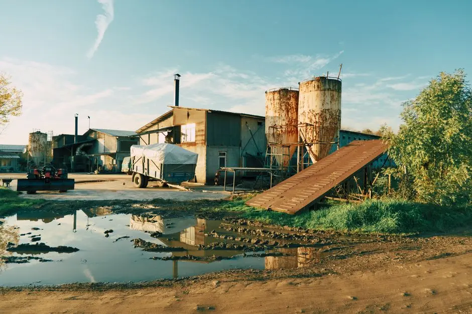
Choice between a DAF system and a lamella clarifier turns on flow, solids density, and bay width. DAF fits fluoride-rich or oily streams at hydraulic loading rates of 4-25 m/h. Lamella units suit dense metal-hydroxide solids and brownfield bays under 6 meters, where surface loading of 20-40 m/h keeps the footprint tight.
Either solids path still needs dewatering on a plate and frame filter press. Polymer at 0.5-2 mg/L typically yields a 25-35% dry-solids cake, which is the usual target for TCLP disposal screening. Selection checklist for Stage 3: peak m³/h, solids settleability jar tests, available bay width, oil-and-grease concentration, sludge haul cost, and spare-parts lead time.
IX vs RO Polishing and When Reuse Pays Back
Ion exchange suits trace-metal polishing below about 50 m³/h throughput. Reverse osmosis becomes the default when the fab targets 50% or greater water reuse. Upstream of RO, a Multi-Media Filter for Water Treatment trims residual turbidity and protects membranes after clarification. An industrial RO polishing system delivers 75-95% recovery for cooling-tower makeup or scrubber feed.
Chromium-based process lines need a dedicated Cr(VI) reduction stage with bisulfite at pH 2-3 before polishing. Continuous online checks such as ICP-OES or XRF verify effluent stays under the local SUO. Where rinse water must stay low in particulates before final polish, the same Multi-Media Filter for Water Treatment is the practical guard filter most EPC packages specify.
PFAS Contingency for 2026 Semiconductor Designs
The Clean Water Standards for PFAS Act directs EPA to propose discharge limits for the electrical and electronic components industry (NAICS 3344) by December 31, 2025. Semiconductor lines often use more than 200 PFAS types, including PFPE and PTFE, so trains without PFAS removal capacity risk early obsolescence. Designs for 2026 should hold about 20% footprint and CapEx contingency for GAC contactors at 10-15 minute empty bed contact time or for foam fractionation. For a parallel regional layout, see our Durham NC semiconductor pretreatment guide.
Who This Is For and Next Step
This guide is for process engineers, EPC leads, and procurement teams sizing pretreatment for Santa Clara County fabs. It is not a substitute for the current SUO text or a site-specific permit. If you need a mass-load based dosing and solids train matched to your POTW ceilings, request a pretreatment design review with your flow sheet and local limit table.
Frequently Asked Questions
Which POTW local limit governs my facility?
Your collection-system connection decides the binding SUO among Palo Alto RWQCP, San Jose-Santa Clara RWF, and Sunnyvale WPCP. Design to that ordinance’s fluoride, metals, ammonia, and oil-and-grease ceilings, not only to 40 CFR 413 categorical floors. Confirm the current permit language before freezing hydraulic and chemical setpoints. Always size to the strictest chemistry that your waste profile can trigger.
What is the recommended design basis for fluoride removal?
Use calcium-driven precipitation with CaCl₂ at a 1.2-1.5 stoichiometric ratio and hold pH at 6.5-7.5. Size the dosing skid on peak kg/day fluoride mass load, not average flow, because semiconductor batch tools commonly spike 3-5 times daily averages. Pair the reactor with continuous fluoride ISE on the effluent header. That pairing keeps monthly DMRs inside the local ceiling.
How do I decide between a DAF and a lamella clarifier?
Select DAF when influent exceeds about 150 m³/h or when oil and grease dominate the solids. Choose a lamella clarifier when bay width is under 6 meters and the solids are dense metal hydroxides that settle on inclined plates. Compare hydraulic loading—DAF at 4-25 m/h versus lamella at 20-40 m/h—against your available footprint. Then confirm sludge cake targets on the filter press.
Do I still need segregation if my average fluoride is low?
Yes—average fluoride can look compliant while etch dumps drive short spikes that breach the SUO. Segregating wet-etch from CMP and developer drains preserves the pH 6-8 window for CaF₂ and the pH 9-10.5 window for metal hydroxides. Mixed drains commonly cut fluoride removal by 40-60% when pH drifts, so lock segregation into the piping isometric before concrete is poured.
When does RO polishing pay back versus ion exchange?
Ion exchange is usually enough for trace metals below about 50 m³/h. RO pays when the fab needs 50% or greater reuse and can use 75-95% recovery permeate for cooling towers or scrubbers. Add Cr(VI) reduction upstream if chromium chemistry is present. Keep online metals verification tied to the local SUO, not to a monthly grab alone.