What governs chemical-plant discharge to the Skokie sewer
Chemical plants near Skokie discharge to the Metropolitan Water Reclamation District of Greater Chicago (MWRD) sewer system and must satisfy a three-layer pretreatment framework: federal categorical standards under 40 CFR Part 414, MWRD's Sewage Use Ordinance local limits, and Skokie backflow-prevention rules. The standard equipment train is equalization → pH neutralization → dissolved air flotation (DAF) for oils and suspended solids → chemical destruction (alkaline chlorination for cyanide, oxidation for sulfide) → multimedia filtration → continuous monitoring, with daily self-monitoring reports filed to MWRD.
The MWRD receives and treats all sewage from the Village of Skokie, and the District operates a 24-hour hotline to report hazardous-material dumping into the sewer. For any chemical plant, that hotline is the practical boundary between a routine exceedance and a compliance event. At the federal level, EPA Categorical Pretreatment Standards under 40 CFR Part 414 cover Organic Chemicals, Plastics, and Synthetic Fibers (Subpart C) and Inorganic Chemicals manufacturing (Subpart F), with subcategory-specific daily-maximum and monthly-average limits for BOD, TSS, COD, total toxic organics, and pH. Where a 40 CFR Part 414 limit is more stringent than the corresponding MWRD local limit, the categorical standard controls; MWRD enforces the gap. Site-issued discharge permits carry sampling/monitoring schedules, surcharges for excess BOD/TSS/FOG loading, and the District's right to halt acceptance for repeat violations.
Skokie layers building-level enforcement on top: the Village's Backflow Prevention Program requires devices on any service connection that poses a cross-connection risk, and Skokie's source-water lead is <5 ppb, so any industrial discharge that could raise lead at the tap is heavily scrutinized. MWRD passed its first PFAS policy in February 2023; chemical plants should expect PFAS monitoring asks to migrate into permit renewals over the next permit cycle. These requirements must be integrated to ensure proper equipment selection.
Typical MWRD local discharge limits chemical plants must meet
Local limits in the MWRD service area run tighter than national categorical defaults for several parameters that matter to chemical plants, particularly FOG, cyanide, and pH excursion range. The numbers below represent the design basis most pretreatment engineers in the greater Chicago area use when sizing a chemical-plant train.
| Parameter | MWRD local limit (typical) | Design implication |
|---|---|---|
| pH | 5.0–10.0 (instantaneous) | Two-stage acid/base neutralization on PLC-controlled dosing loops with redundant probes |
| Total cyanide | <0.2 mg/L | Alkaline chlorination at pH 10–11 with ≥30 min contact time, ORP feedback |
| Oil & grease | <100 mg/L daily max (50 mg/L common in industrial permits) | DAF with polymer addition; skim to dedicated FOG drum |
| Total suspended solids | <250 mg/L daily max; surcharge above 200 mg/L | Coagulation/flocculation + DAF or lamella clarifier |
| Flash point | >140°F (60°C) for any liquid waste | Solvent segregation; flammable-waste handling per MWRD permit conditions |
| Cadmium | <0.1 mg/L | Source control; hydroxide precipitation in equalization |
| Total chromium | <1.0 mg/L | Hexavalent Cr reduction with NaHSO3 or ferrous sulfate before precipitation |
| Lead | <0.5 mg/L | Co-precipitation with hydroxide sludge; tightened given Skokie source-water lead scrutiny |
| Nickel | <1.0 mg/L | Hydroxide precipitation at pH 9–10 |
| Zinc | <2.0 mg/L | Hydroxide precipitation; avoid high-pH excursions that re-solubilize |
| Temperature | <150°F at monitoring point | Cooling/quench ahead of equalization if process runs hot |
For a deeper cross-reference on the federal side, see this EPA and US wastewater discharge standards reference. Plants with categorical applicability under 40 CFR Part 414 should overlay the subcategory effluent limits on top of the table above — the most stringent value at each parameter is the operating target.
The seven-stage pretreatment train for a Skokie chemical plant
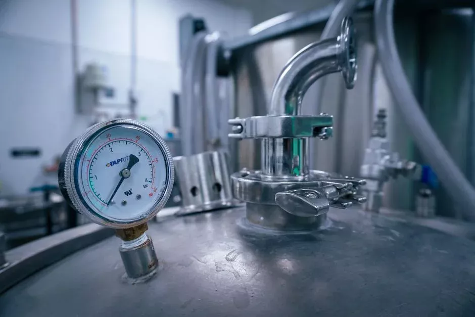
The conventional train for a chemical plant discharging to MWRD is physical-chemical; biological treatment belongs to the receiving water reclamation plant (Calumet or Stickney), not the industrial user. This sequence ensures each unit operation protects the one downstream of it.
Stage 1 — Equalization. A 24–48 hour buffer tank with mechanical or jet mixing damps batch dumps from reactors, CIP cycles, and tank-farm displacements. Hydraulic sizing should target 1.5× peak daily flow so a worst-case batch can ride out without overflowing the equalization basin or tripping a downstream diversion.
Stage 2 — Mechanical screening. A rotary bar screen for headworks protection removes rags, packaging fragments, agglomerated solids, and stray gaskets before they foul chemical dosing pumps and plug DAF nozzles. Bar spacing is typically 3–6 mm for chemical-plant service.
Stage 3 — pH adjustment. Two-stage neutralization with sulfuric acid (or HCl) for caustic sidestreams and sodium hydroxide for acidic sidestreams, fed by PLC-controlled chemical dosing skids with redundant pH probes. Two stages prevent the overshoot that single-stage neutralization produces when strong acid and strong base are mixed in-line.
Stage 4 — Coagulation/flocculation. Coagulant dosing — typically polyaluminum chloride (PAC) at 50–200 mg/L or ferric chloride at 100–300 mg/L — followed by a flocculant polymer (0.5–3 mg/L cationic or anionic depending on the colloidal charge). This step allows the DAF or lamella clarifier to capture the emulsified oils and fine suspended solids that raw equalized wastewater carries.
Stage 5 — Dissolved air flotation. A DAF system for oil and suspended solids removal is the workhorse for chemical-plant FOG. Typical performance is 90–95% FOG removal and 85–95% TSS removal at hydraulic loading rates of 15–25 m3/m2·h when polymer-conditioned. Skim is routed to a dedicated FOG drum for off-site disposal. For plants with high-density sludges or significant inorganics, a high-efficiency sedimentation tank may precede or replace the DAF — the trade-off is covered in this DAF vs. clarifier selection guide for chemical wastewater.
Stage 6 — Chemical destruction. Cyanide is oxidized to cyanate and then to CO2 and nitrate by alkaline chlorination at pH 10–11 with a target ORP of +300 to +350 mV and ≥30 min contact; sodium hypochlorite or chlorine gas both work, with hypochlorite being the safer choice for plants without scrubber infrastructure. Sulfide is oxidized similarly with chlorine or hydrogen peroxide. Hexavalent chromium is reduced to trivalent with NaHSO3 or ferrous sulfate at pH <3, then co-precipitated as Cr(OH)3 in the neutralization stage. pH and ORP feedback control are essential for this stage.
Stage 7 — Polishing multimedia filtration and on-line monitoring. Polishing multimedia filters (anthracite over sand over garnet) take out any residual TSS that slipped past the DAF. Continuous on-line analyzers for pH, conductivity, flow, TOC, and total residual chlorine feed the plant SCADA and trigger automatic diversion to recycle if any parameter drifts out of band. The treated effluent discharges to the sanitary sewer through an accessible sampling port; sludge from the DAF and clarifier is routed to a sludge dewatering filter press for cake generation prior to off-site disposal.
Self-monitoring, sampling, and reporting MWRD requires
MWRD requires daily self-monitoring reports (SMRs) covering flow, pH, TSS, oil & grease, and any categorical pollutant above the trigger threshold identified in the site discharge permit. The reports go to MWRD's pretreatment program on a calendar-day cadence regardless of whether the plant operates that day — zero-flow days are still reported.
Sampling design follows the categorical standards under 40 CFR Part 414 for plants subject to them: 24-hour flow-proportional composite samples for BOD, TSS, COD, and total toxic organics; 8-hour composites or grabs for transient parameters like total cyanide, total amenable cyanide, sulfides, phenols, and volatile organics. Composite samplers must be MWRD-approved, and chain-of-custody documentation runs from sample collection through laboratory receipt. Records retention is a minimum of three years; permit writers typically extend that to the active permit life plus three years for any parameter that drove a permit limit.
Continuous on-line instrumentation — pH, conductivity, flow, and total residual chlorine at minimum — is a permit condition for any categorical industrial user, and the data feed is typically required to be telemetered to MWRD in addition to the plant SCADA. MWRD's 24-hour dumping hotline is the official channel for any noncompliant bypass or upset; failure to notify within 24 hours is a permit violation independent of the original event. For petroleum-sector comparison points that overlap on the categorical side, this pretreatment compliance walkthrough for petroleum plants lays out an analogous reporting structure.
Designing a 2026-compliant system without overspending
Chemical plants often over-specify biological treatment when designing for MWRD, which is unnecessary because the District handles the activated-sludge process. The industrial user is responsible only for physical-chemical pretreatment to the local-limits table above, which removes 30–50% of the biological-stage CAPEX a plant would otherwise size for in a direct-discharge scenario.
Match DAF hydraulic capacity to peak 2-hour flow, not the daily average — chemical plants tend to discharge in batches tied to reactor cycles, not continuously. Specify redundant dosing pumps on the parameters that trigger automatic diversion (pH, total Cl2); a single-pump failure on either of those is a permit violation. Factory-tested, skidded PLC-controlled chemical dosing skids shorten field installation and reduce the engineering hours charged against the permit schedule.
Plan for forward compatibility. If a future zero-liquid-discharge (ZLD) trajectory is plausible — driven by PFAS, surcharges, or water-reuse economics — leave hydraulic headroom and floor space for a downstream reverse-osmosis unit or evaporator, and oversize the equalization tank by one stage to buffer RO reject swings. Plants that skip this step pay double later when they have to re-permit for the expanded footprint.
Frequently Asked Questions
What is the difference between EPA categorical standards and MWRD local limits, and which one applies to a Skokie chemical plant?
EPA Categorical Pretreatment Standards under 40 CFR Part 414 set subcategory-specific effluent limits for Organic Chemicals, Plastics, and Synthetic Fibers (Subpart C) and Inorganic Chemicals (Subpart F) manufacturers. MWRD's Sewage Use Ordinance is the local enforcement instrument — it carries the site discharge permit, the sampling and reporting cadence, and any local limits (FOG, cyanide, flash point) that are tighter than the federal floor. Both apply. The more stringent value at each parameter is the operating
Frequently Asked Questions
What are the MWRD discharge limits for chemical plants in Skokie, IL?
Chemical plants in Skokie must comply with the Metropolitan Water Reclamation District of Greater Chicago (MWRD) Sewage and Waste Control Ordinance. Specific local limits for heavy metals often include caps such as 0.2 mg/L for cadmium, 1.0 mg/L for copper, 2.0 mg/L for lead, and 0.5 mg/L for mercury, depending on the specific industrial category. Facilities must also maintain a pH range between 5.0 and 12.0 standard units to prevent damage to the sewer infrastructure.
Do chemical plants discharging to MWRD need biological treatment?
Whether biological treatment is required depends on the chemical oxygen demand (COD) and biochemical oxygen demand (BOD) of the plant's effluent. If the wastewater contains high concentrations of organic compounds that exceed local surcharge thresholds—typically defined by BOD levels above 250 mg/L or suspended solids above 300 mg/L—the facility may need to install aerobic or anaerobic treatment systems to reduce organic loading before discharge.
How do you treat cyanide in industrial wastewater to meet sewer limits?
To meet the strict MWRD cyanide limits, which are often set at or below 0.19 mg/L for total cyanide, chemical plants typically employ alkaline chlorination. This process involves raising the wastewater pH to above 10.5 and adding sodium hypochlorite to oxidize cyanide into cyanate and eventually into harmless nitrogen and carbon dioxide. Advanced oxidation processes using hydrogen peroxide or ozone may also be implemented for more complex waste streams.
What does a chemical plant need to install to meet Skokie pretreatment rules?
Facilities must install an accessible industrial monitoring manhole to allow MWRD inspectors to collect representative samples of the effluent. Depending on the chemical processes involved, plants often need to install equalization tanks to normalize flow and pH, oil-water separators for hydrocarbon removal, and specialized filtration or precipitation units to ensure heavy metals and other regulated pollutants remain below the mandated mass-loading limits.
Is a pretreatment permit required for chemical manufacturers in the MWRD service area?
Yes, any chemical manufacturer classified as a Significant Industrial User (SIU) must obtain a Wastewater Discharge Permit from the MWRD. This permit specifies the facility’s unique discharge requirements, monitoring frequencies, and reporting obligations. Failure to obtain or adhere to the conditions of this permit can result in significant administrative fines and the potential revocation of the right to discharge into the public sewer system.