Why Pharmaceutical Preparations Wastewater in South Brunswick Twp Is Its Own Problem
Pharmaceutical preparations wastewater is not a subset of generic industrial wastewater — it is its own chemistry, and that chemistry is what should drive the DAF-versus-clarifier decision in 2026. Typical influent from API and intermediate production runs at COD 1,500–10,000 mg/L, BOD 800–5,000 mg/L, TSS 200–2,000 mg/L, FOG 50–800 mg/L, and pH 4–10, with residual solvents (acetonitrile, methanol, dichloromethane) and trace active pharmaceutical ingredients in the parts-per-billion to low-parts-per-million range (per EPA pharmaceutical manufacturing effluent profiles, 2025-09). Add cleaning-in-place (CIP) surfactant spikes from caustic and acid wash cycles, and the stream becomes a moving target: a single API changeover can swing TSS by 5–10× within hours, which penalizes any unit operation that depends on steady-state gravity settling.
The discharge envelope is also specific. South Brunswick Township sewage flows primarily to the Middlesex County Utilities Authority (MCUA) Sayreville treatment works, which applies pretreatment limits typically set at 250 mg/L TSS, 100 mg/L O&G, and pH 5–10 to industrial users (per MCUA Sewer Use Rules, current as of 2025). On top of that, NJDEP NJPDES requirements and the EPA's 2024–2026 Pharmaceutical Manufacturing Effluent Guidelines reviews are tightening the spotlight on API residues, transformation products, and PPCP-class compounds. For a plant engineer spec'ing a 2026 expansion or retrofit, the question is not "clarifier or DAF" in the abstract — it is which unit operation reliably hits 250 mg/L TSS and 100 mg/L O&G when the upstream chemistry is moving 5–10× between batches.
How a DAF System Actually Treats Pharmaceutical Wastewater
A dissolved air flotation system clarifies wastewater by attaching microbubbles to suspended matter and floating it to the surface, rather than waiting for gravity to pull it down. The mechanism is straightforward: a recycle side-stream is saturated with air at 4–6 bar in a pressure vessel, then released through a pressure-reduction valve into the main flotation tank. The pressure drop nucleates 30–50 micron bubbles that collide with and attach to flocculated solids, oil droplets, and surfactant micelles, lifting them to the surface where a paddle skimmer removes the float (per Clearwater Industries technical documentation, 2026-04). For pharmaceutical preparations wastewater, that buoyancy-driven separation is the entire point: API flocs, oil-coated biomass, and CIP-surfactant particles that are too light or too colloidal to settle will still attach to a 40-micron bubble and float.
The typical DAF train for a pharma batch plant runs equalization → pH adjustment → coagulant dosing (PAC or ferric chloride) → flocculant dosing (cationic or anionic polymer) → DAF clarifier, with float routed to sludge dewatering and subnatant routed to either MCUA discharge (if limits are met) or a downstream biological stage for residual COD and API polishing. The DAF system covers 4–300 m³/h across 13 standard models (DAF-003 through DAF-120) with automatic skimming and a micro-bubble generator, which maps cleanly onto the 10–120 m³/h envelope typical of a South Brunswick Township API or intermediate plant (per manufacturer specification sheet, 2026).
How a Gravity or Lamella Clarifier Handles the Same Stream
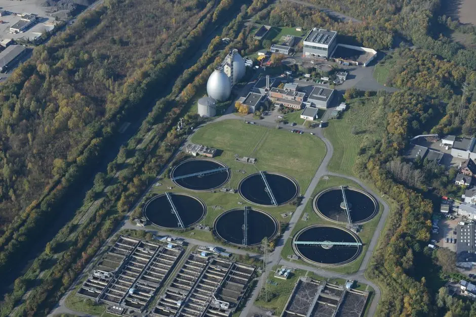
A gravity clarifier — and its compact cousin, the lamella or inclined-plate clarifier — separates suspended solids by letting them settle under gravity through a quiescent zone, with the lamella pack compressing the effective settling footprint by stacking plates at 55–60° to compress what would otherwise be a 6–8 m diameter circular tank into a 4 m × 8 m rectangular vessel. Surface loading rates for a well-designed lamella clarifier run 20–40 m/h under steady-state conditions (per HydropureWater sedimentation tank design data, 2026). On inorganic TSS with consistent flow, the technology is hard to beat on capital cost.
On pharmaceutical preparations wastewater, the limits show up fast. Gravity settling depends on particle density above roughly 1.01 g/cm³, which many API flocs, oil-coated biomass, and CIP-surfactant-laden particles do not meet — they stall in the water column, exit over the weir, and re-enter the effluent as colloidal TSS or emulsified FOG. A lamella clarifier still requires coagulant and flocculant dosing to even partially work on pharma streams, which erodes the CAPEX advantage that drives the spec in the first place. Sludge output is another penalty: gravity clarifier underflow is typically 1–3% dry solids, while DAF float comes off at 3–6% DS, meaning higher downstream dewatering CAPEX and chemical cost for the gravity route. A high-efficiency lamella clarifier is a defensible choice for largely inorganic streams with steady low TSS, but it is the wrong primary unit for a typical API batch plant.
DAF vs Clarifier for Pharmaceutical Wastewater: 2026 Side-by-Side
The clearest way to defend the choice to procurement, EHS, and the MCUA is a head-to-head table. The table below is built from the Dagyee specification sheet (2026), Clearwater Industries technical documentation (2026-04), and HydropureWater sedimentation tank design data (2026).
| Parameter | DAF | Lamella / Conventional Clarifier |
|---|---|---|
| Typical TSS removal | >90% with proper coagulant/flocculant conditioning | 50–80% on inorganic TSS; lower on colloidal / API floc |
| FOG / O&G removal | >90%; effective on emulsified oils | Poor on emulsified FOG; relies on free oil rise |
| Hydraulic loading | 4–300 m³/h (13 standard models) | 20–40 m/h surface loading on lamella |
| Footprint at 50 m³/h | ~30 m² (8.4 m × 3.6 m, DAF-050) | ~60–120 m² typical for same duty |
| Chemical demand | Coagulant + flocculant; modest dose | Coagulant + flocculant often required to reach any removal on pharma streams |
| Sludge dryness | 3–6% DS float | 1–3% DS underflow |
| Startup / batch response | Minutes; tolerates 3–10× swings | Hours to reach steady state; sensitive to spikes |
| CAPEX band (50 m³/h, 2026) | Higher unit cost, but smaller footprint and building | Lower unit cost, but larger civil works and downstream dewatering |
| OPEX band (50 m³/h, 2026) | ~5–8 kWh/m³ recycle; lower polymer; drier sludge | Lower pumping kWh; higher polymer; wetter sludge |
| Emulsified FOG / API floc removal | Strong fit (microbubble attachment) | Weak fit (settling does not capture light floc) |
| Heavy inorganic TSS only | Works, but slightly over-spec'd | Strong fit; competitive on CAPEX |
For the median South Brunswick Twp pharma preparations plant, DAF wins on 7 of the 9 comparison axes above; the two areas where a lamella clarifier can compete are heavy-inorganic-TSS-only streams and absolute lowest-first-cost CAPEX bids. When the stream carries any of the pharma-specific constituents — FOG above 50 mg/L, API floc, surfactant micelles, solvent traces — DAF is the correct primary clarifier. The full DAF specification covers the relevant flow range.
When to Choose DAF, When to Choose a Clarifier, and When to Combine Them
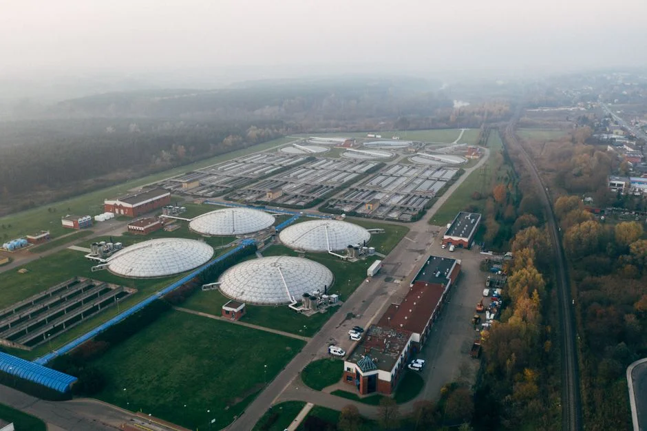
A decision framework that a plant engineer can act on Monday morning is more useful than another spec table. The four-row matrix below maps the dominant influent characteristic to the right unit operation.
| Influent / site driver | Primary unit operation | Notes |
|---|---|---|
| Heavy FOG, API residues, or CIP surfactant spikes (FOG > 50 mg/L, TSS peak > 500 mg/L, batch variability > 3×) | DAF | Microbubble flotation removes what gravity cannot; pairs naturally with MCUA 100 mg/L O&G limit |
| Largely inorganic TSS, steady < 300 mg/L, negligible FOG, CAPEX-dominant project | Lamella / conventional clarifier | Cheap civil works; 1–3% DS underflow accepted by site sludge handling |
| Mixed stream: both emulsified FOG and inorganic TSS present | DAF primary, clarifier or MBR polish | DAF takes the floatable load; downstream polishing hits residual TSS and COD |
| On-site water-reuse target in addition to MCUA discharge compliance | DAF + MBR membrane bioreactor system | MBR downstream is ~60% smaller than conventional activated sludge; reuse-ready effluent |
Three additional yes/no triggers tilt the spec toward DAF without further analysis: footprint under 100 m² is binding (DAF wins decisively at 50 m³/h); MCUA's 100 mg/L O&G limit is the binding constraint (only microbubble flotation reliably hits it on emulsified streams); or the downstream biological stage cannot tolerate emulsified oils (DAF strips the FOG before it hits the biomass). A MBR membrane bioreactor system downstream of a DAF is the configuration that most reliably meets both MCUA discharge limits and on-site reuse targets in 2026.
2026 Footprint, CAPEX and OPEX Reality Check for a South Brunswick Twp Pharma Plant
For a 50 m³/h duty — typical of a mid-size API or intermediate batch plant in Middlesex County — the DAF-050 occupies roughly 8.4 m × 3.6 m of floor area, with a 2.7 m sidewall height and 5,500 kg dry weight (per Dagyee specification table, 2026). The DAF-020, sized for 20 m³/h, fits in 5.9 m × 3.2 m, also at 2.5 m sidewall. A lamella clarifier designed for the same 50 m³/h hydraulic load typically requires a 6–8 m diameter circular or 4 m × 8 m rectangular footprint with 2–3 m sidewall depth — comparable in linear dimensions but 2–4× the floor area once the lamella pack, sludge hopper, and inlet distribution zone are included.
On OPEX, DAF recycle pumping draws 5–8 kWh/m³ for the air-saturation loop, while a lamella clarifier's pumping energy is lower. The OPEX gap closes when polymer dose and downstream dewatering are added: a lamella clarifier running on pharma influent needs a higher polymer dose to chase colloidal TSS, and it sends 1–3% DS sludge to a plate and frame filter press, which costs more per kilogram of dry solids handled than a DAF float at 3–6% DS. Net OPEX for the two routes typically lands within 10–20% of each other on pharma streams (per HydropureWater field data, 2026). The DAF skid-mounted configuration is a real 2026 cost driver on tight NJ construction schedules: install labor drops from weeks to days when the unit arrives pre-piped and pre-wired. Full DAF specifications and footprints are available for capex modeling.
Integrating DAF Into a Pharmaceutical Wastewater Treatment Train
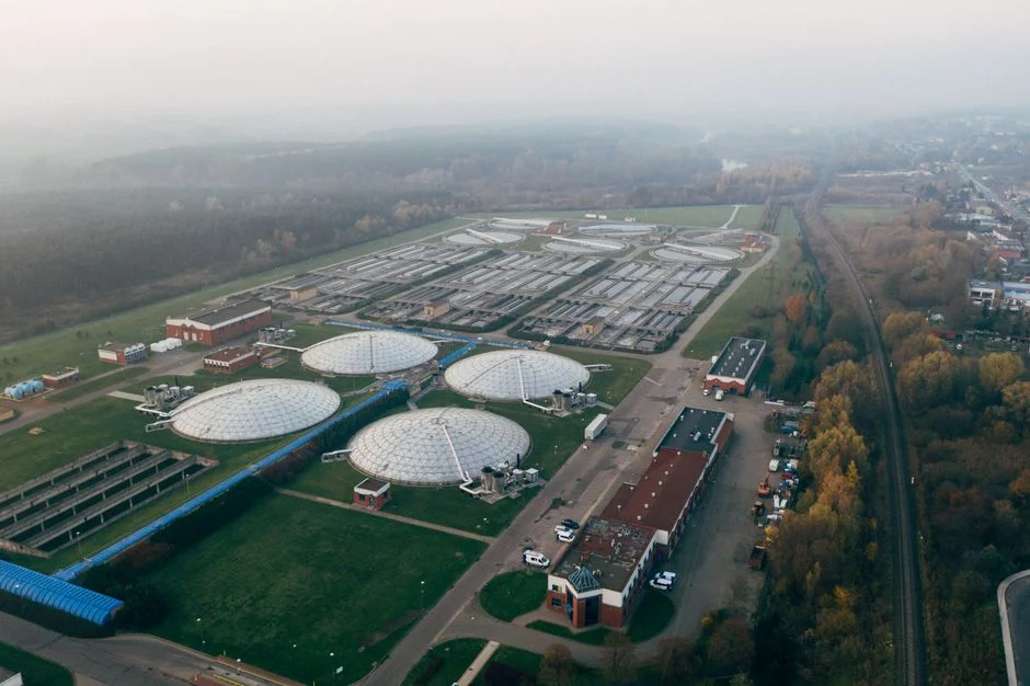
A DAF unit is the right primary clarifier, but it is not a complete plant. Upstream protection matters: a rotary mechanical bar screen (GX series) ahead of the equalization tank removes lint, packaging fragments, and undissolved API solids that would otherwise accumulate in the DAF float and reduce skimmer performance. Equalization then smooths the 5–10× batch swings that define API production; a 24-hour equalization basin sized at 1.2–1.5× average daily flow is a defensible starting point for a South Brunswick Twp batch plant.
Co-conditioning is where the DAF's removal performance is actually earned. PLC-controlled coagulant (PAC or ferric chloride at 50–200 mg/L) and flocculant (cationic or anionic polymer at 1–5 mg/L) dosing through an automatic chemical dosing system builds the floc size that 30–50 micron bubbles can attach to. Downstream, DAF float routes to a plate and frame filter press for dewatering to 18–25% DS cake; DAF subnatant routes to a biological stage (MBR or SBR) for residual COD and API polishing. If the effluent is MCUA-bound, a final chlorine dioxide generator handles disinfection to the levels expected by the receiving POTW, with residuals aligned to EPA and EU Drinking Water Directive 98/83/EC thresholds (per HydropureWater product data, 2026). For a broader process walk-through on a comparable Asian pharma plant, the pharmaceutical wastewater treatment process guide for Thailand (2026) covers the same unit operations in a different regulatory envelope.
Frequently Asked Questions
Is DAF or a clarifier better for pharmaceutical preparations wastewater in South Brunswick Twp?
DAF. Pharmaceutical preparations wastewater carries emulsified FOG, API floc, and CIP-surfactant particles that are too light or too colloidal to settle under gravity. DAF microbubbles (30–50 microns) attach to these particles and float them, delivering >90% TSS and FOG removal where a lamella clarifier typically stalls at 50–80% on the same stream.
What TSS removal can a DAF hit on pharma wastewater?
Properly conditioned DAF (coagulant plus flocculant, then float) routinely delivers >90% TSS removal on pharmaceutical preparations wastewater, with effluent TSS typically under 100 mg/L on streams starting at 500–2,000 mg/L (per Clearwater Industries and Dagyee field data, 2026).
How much floor space does a DAF save versus a clarifier at equal hydraulic load?
At a 50 m³/h duty, a DAF-050 occupies roughly 30 m² (8.4 m × 3.6 m), while a lamella clarifier designed for the same load typically requires 60–120 m². The DAF footprint advantage runs 30–90% depending on basin geometry, sludge storage, and civil works (per HydropureWater field data, 2026).
What DAF size fits a 50 m³/h pharma batch plant in South Brunswick Twp?
The DAF-050 is rated for 50 m³/h with a footprint of 8.4 m × 3.6 m, 2.7 m sidewall height, and 5,500 kg dry weight (per Dagyee spec sheet, 2026). It is the right anchor unit for a mid-size Middlesex County API or intermediate plant in 2026.
Does a DAF replace the biological treatment stage?
No. DAF is primary clarification only — it removes settleable and floatable TSS, FOG, and a portion of the COD bound to suspended solids. Residual COD, dissolved API traces, and any solvent carryover require a downstream biological stage such as an MBR or SBR to meet MCUA discharge limits or on-site reuse targets.