Why Tank Bottom Water Needs Its Own DAF Configuration
Tank bottom water is best treated with a recycle-flow pressurization DAF configured at 10–25% recycle, 350–500 kPa saturator pressure, 8–12% air-to-water ratio, and 20–100 μm micro-bubbles discharged through nozzles near the tank bottom. A 15–25 minute hydraulic residence time with mechanical float skimming and clarified water draw from the tank bottom delivers 80–90% oil and TSS removal suitable for reuse polishing or downstream biotreatment.
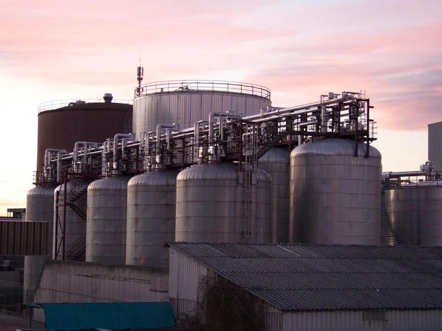
Tank bottom water is the settled aqueous phase drawn from crude oil, slop oil, diesel, lube, and chemical storage tanks during routine drain-off or cleaning events. It is a distinct feed class: typical analyses show 200–2,000 mg/L TSS, 100–5,000 mg/L oil & grease, frequent emulsified layers, and a viscosity often 1.5–3× higher than general refinery wastewater. Unlike separator water from an API or CPI unit, tank bottoms carry rag, grit, and pumpable sludge that arrives in slug loads of 50–200 m³ over a 2–4 hour window after each tank cleaning cycle.
A standard refinery DAF sized for separator water is not a finished design for this feed. Durban University of Technology (DUT) jar and pilot work on refinery oily wastewater used pH 5, 50 mg/L coagulant, 10% A/W ratio, and 350 kPa saturator pressure as the optimum, but those numbers were derived on settled separator water, not on a 2,000 mg/L TSS tank-bottom draw with intermittent emulsified slugs. The configuration decision has to be made around two end states: closed-loop reuse (wash water make-up, cooling tower make-up, boiler feed polish) where DAF is a pre-treatment step, and compliant discharge where DAF effluent feeds a biotreatment train or sewer. For both paths, the DAF itself is the same unit, but the recycle ratio, float handling, and downstream polishing change. The right starting point is a dissolved air flotation system sized explicitly for the tank-bottom feed envelope, not borrowed from a general oily-water P&ID.
Feed Characterization and Pre-Treatment Train
Tank bottom water must be characterized and pre-conditioned before it reaches the flotation chamber, or the saturator nozzles and float skimmer will fail within weeks. Pull samples across at least three draw events and across three vertical positions in the tank: the floating oil pad (typically 80–95% oil, recovered as skimmings), the middle emulsified layer (the layer that breaks in a DAF and defines the unit's oil load), and the bottom sludge layer (3–8% solids, 20–40% oil, the largest single feed stream by mass). The emulsified middle layer is what the DAF sees as a continuous feed; the bottom sludge is what the float skimmer recovers.
The pre-treatment train has four fixed steps. First, coarse screening to 6 mm followed by fine screening to 0.5–1 mm using a rotary mechanical bar screen to protect the recycle pump and saturator nozzles from rag and grit that would otherwise score the orifice plates. Second, equalization for 24–48 hours with mild mechanical agitation (tip speed below 1.5 m/s); air sparging is contraindicated because it emulsifies the floating oil pad and defeats the DAF. Equalization also dampens the 50–200 m³ slug loads that follow tank cleaning. Third, pH adjustment to 5–7 using sulfuric acid or caustic through an automatic chemical dosing system; DUT data confirms pH 5 is optimal for oily feeds, but metalworking tank bottoms (chromium, nickel, zinc in solution) need pH 7–8 to keep heavy metals dissolved and prevent hydroxide precipitation in the saturator. Fourth, coagulation with polyaluminium chloride (PAC) at 30–50 mg/L for oily feeds, followed by anionic polyacrylamide flocculant at 1–3 mg/L for bridging; the PAC dose drops 30–40% in the Acid–Coagulation–DAF configuration versus post-DAF dosing per the DUT study.
Core DAF Configuration: Saturator, Recycle, and Bubble Size
Four numbers go on the P&ID: saturator pressure, recycle ratio, air-to-water ratio, and micro-bubble size. Each has a defensible range tied to either published data or stated engineering convention.
Saturator pressure: the working window is 350–500 kPa. DUT OFAT work found 350 kPa optimal for settled separator water; BBD optimization extended the optimum to 300–425 kPa on a batch scale, but tank bottom water with oil loads above 1,000 mg/L benefits from 450–500 kPa because Henry's law gives more dissolved air per unit of recycle, which translates directly to higher bubble density in the flotation chamber. Above 500 kPa the saturator retention time has to grow to keep the water fully saturated, and pump energy cost rises faster than removal efficiency.
Recycle flow: 10–25% of clarified effluent is pressurized in a packed or perforated-tube saturator with hydraulic retention of at least 60 seconds at design pressure (per the recycle-flow pressurization system described in the Green and Sustainable Chemistry review, S2). The lower end (10%) suits free-oil feeds below 500 mg/L; the upper end (25%) is used for emulsified or chemically treated feeds, and for any stream heading to a reuse polishing step where a 5–10 mg/L incremental improvement in subnatant oil justifies the higher saturator energy cost.
Air-to-water ratio: 8–12% by volume. The DUT BBD study set 8–12% as the operating range; 8% is appropriate for free-oil feeds, 12% for emulsified or polymer-treated feeds. Below 8% bubble density is too low to carry a 30–100 mm float layer at the design surface loading; above 12% the excess air breaks through as large bubbles and re-entrains float.
Micro-bubble formation: 20–100 μm diameter at the nozzle discharge, produced by releasing the pressurized recycle through pin nozzles or needle-valve manifolds into the flotation tank at near-atmospheric pressure (S2). Porous plates are avoided on oily tank-bottom feeds because the plate pores foul within 2–4 weeks; pin nozzles can be cleaned in place by back-flushing the recycle line. The nozzle manifold sits below the flotation chamber, discharging into a distribution header that spreads flow across the full tank cross-section so the float rises uniformly and the clarified water is taken from the bottom (S2).
Flotation Tank Hydraulics and Skimming
The flotation chamber sizing is what makes or breaks the removal efficiency. Hydraulic residence time should be 15–25 minutes; DUT jar tests settled on 15 minutes as the optimum flotation time, but continuous pilot work on emulsified feeds extended this to 20–25 minutes to give the bubble–floc agglomerate time to reach the surface. Surface loading rate runs 5–15 m/h; the lower end (5–8 m/h) is mandatory when the DAF subnatant is heading to a multimedia filter or MBR for reuse, and the upper end (10–15 m/h) is acceptable when the effluent feeds a downstream activated sludge or SBR biotreatment train where the biology absorbs the residual oil.
Float layer thickness is controlled at 30–100 mm via an adjustable weir or a mechanical scraper running at 0.5–1.0 m/min; above 100 mm the float compacts, traps water, and re-entrains when the scraper passes. Subnatant draw is from the tank bottom through a launder or perforated laterals, positioned at least 300 mm below the water surface to avoid pulling floated sludge back into the clarified stream. Skimmer selection follows float volume: a full-width beach skimmer for high-float feeds (above 5% of feed volume) typical of crude tank bottoms, or a screw-type skimmer for low-float, high-solids feeds below 3% of feed volume. The table below consolidates the parameters and their operating ranges.
| Parameter | Range for Tank Bottom Water | Notes |
|---|---|---|
| Saturator pressure | 350–500 kPa | 450–500 kPa for oil load >1,000 mg/L |
| Recycle flow | 10–25% of clarified effluent | 10% free-oil, 25% emulsified or reuse polishing |
| Air-to-water ratio | 8–12% by volume | 8% free-oil, 12% emulsified or polymer-treated |
| Micro-bubble diameter | 20–100 μm | Pin nozzles preferred over porous plates on oily feeds |
| Hydraulic residence time | 15–25 minutes | 20–25 minutes for emulsified feeds |
| Surface loading rate | 5–15 m/h | 5–8 m/h for reuse polishing, 10–15 m/h pre-biotreatment |
| Float layer thickness | 30–100 mm | Controlled by weir or scraper at 0.5–1.0 m/min |
| Saturator retention | ≥60 seconds at design pressure | Packed or perforated-tube saturator (S2) |
Reuse vs Discharge: Choosing the Right Downstream Path
The DAF subnatant typically leaves the unit at 10–50 mg/L oil and 30–80 mg/L TSS, and the next step depends entirely on whether the water is being reused or discharged. For reuse paths (wash water make-up, cooling tower make-up, irrigation), 20–50 mg/L oil and 30–80 mg/L TSS from the DAF is not clean enough; closed-loop process water reuse typically caps oil below 5 mg/L and TSS below 10 mg/L, and boiler feed polish demands under 1 mg/L oil and under 5 mg/L TSS. The standard train is a multi-media filter followed by an MBR membrane bioreactor or UF polishing step; this combination is consistent with the broader DAF polishing train used in analogous oily-water reuse applications such as the DAF configuration for paper machine seal water and the DAF configuration for solvent stripper dilute water guides.
For discharge paths, 10–30 mg/L oil and 30–80 mg/L TSS from the DAF is suitable for biological polishing in an activated sludge or SBR train, or direct sewer discharge where the local POTW permit allows. The decision rule is straightforward: if the next step is biological, stop at DAF; if the next step is membrane or boiler feed, add a multimedia filter plus MBR or UF. The recycle ratio choice ties directly to the reuse path: 10% recycle is sufficient for discharge-quality effluent, but a reuse polishing train justifies 25% recycle because the 5–10 mg/L oil reduction at the DAF dramatically extends membrane life downstream. The saturator energy penalty for 25% versus 10% recycle (roughly 15–20% of total DAF power) is recovered in lower membrane cleaning frequency and longer membrane service life, particularly on feeds with emulsified oil load above 500 mg/L.
Float Sludge Handling and 2026 Compliance Notes
Float sludge from a tank-bottom DAF is 3–8% of feed volume, at 2–6% dry solids and 30–60% oil content by weight. This is the stream every other DAF guide leaves out, and it is the first thing operators ask about after startup. The standard handling train is a sludge holding tank (12–24 hour retention, mild agitation) feeding a plate-and-frame filter press sized at 8–15 m² of filtration area per m³ of daily float, producing a 25–35% dry-solids cake suitable for off-site disposal. Where the float is oil-rich (crude tank bottoms with oil content above 50%), the float is often returned to a slop oil tank and re-refined rather than sent to sludge dewatering; this recovers the oil value and eliminates the disposal cost.
2026 regulatory framing: oily float sludge from petroleum tank bottoms is typically classified as hazardous waste in most US jurisdictions under RCRA K-waste codes for refinery waste, and the float must be tested for benzene, lead, and total petroleum hydrocarbons before disposal routing is finalized. Confirm local classification with the state environmental agency before commissioning. Filtrate water from the filter press is returned to the DAF feed equalization tank, not to the saturator recycle, because dissolved salts and trace oil accumulate in the saturator and degrade bubble formation over time. A high-efficiency sedimentation tank ahead of the filter press catches fine solids that would otherwise blind the press cloths. Operators should plan float handling capacity for the upper end of the 3–8% range; under-sizing the press is the single most common post-startup retrofit on tank-bottom DAF installations.
Frequently Asked Questions
What DAF configuration treats tank bottom water for reuse or discharge?
Recycle-flow pressurization DAF at 10–25% recycle, 350–500 kPa saturator pressure, 8–12% air-to-water ratio, and 20–100 μm micro-bubbles, with 15–25 minute HRT. This delivers 80–90% oil and TSS removal, leaving 10–50 mg/L oil and 30–80 mg/L TSS in the subnatant for downstream biotreatment or membrane polishing.
What saturator pressure should I specify for a tank-bottom DAF?
Specify 350–500 kPa. Use 350–425 kPa for settled separator-quality tank bottoms with oil load below 1,000 mg/L, and 450–500 kPa for emulsified or high-oil tank-bottom draws above 1,000 mg/L to dissolve sufficient air per unit recycle for stable bubble density.
How much float sludge does a tank-bottom DAF produce, and how is it handled?
Float sludge is 3–8% of feed volume at 2–6% solids and 30–60% oil content. Route it to a holding tank and a plate-and-frame filter press sized at 8–15 m² per m³ of daily float, producing a 25–35% dry-solids cake; oil-rich float above 50% oil can be returned to a slop oil tank for re-refining instead of dewatering.
Does DAF alone meet closed-loop reuse specs for tank bottom water?
No. DAF subnatant at 10–50 mg/L oil and 30–80 mg/L TSS exceeds typical reuse limits of 5 mg/L oil and 10 mg/L TSS. Pair the DAF with a multi-media filter and MBR or UF polishing to reach wash water, cooling tower, or boiler feed specifications.