CASS Process Working Principle: Selector Zone and Cycle Logic
The CASS process working principle is continuous influent via a front selector, then fill, react, settle, decant, and idle in one tank. The selector (5–15% volume) runs high F/M under anoxic or low-DO conditions to favor floc-formers. A liftable decanter replaces the secondary clarifier. Reference plants report CODCr up to 85% and BOD5 up to 95%.
CASS (Cyclic Activated Sludge System), also called CAST — Cyclic Activated Sludge Technology — is a continuously fed, intermittently decanted sequencing batch reactor (SBR) variant. American engineers developed it on top of ICEAS, which itself evolved from classical SBR (source: sinokle.com). One rectangular tank is split lengthwise into a front biological selector and a rear main reaction zone. Aeration, sedimentation, and drainage still run in sequence in one vessel, while influent enters around the clock through the selector.
The liftable decanter at the tank rear replaces the secondary clarifier. The reactor repeats fill / react / settle / decant / idle cycles. Reference U.S. plants report CODCr removal up to 85% and BOD5 removal up to 95% (source: sinokle.com). That envelope matches continuous-flow CAS in a footprint typically 20–30% smaller, because no separate clarifier or sludge-return pumping station is needed. Classical SBR is batch-fed and needs equalization for continuous municipal service. CASS absorbs diurnal flow through the selector, which is why it displaced batch SBR in most new 1,000–50,000 m³/day municipal and industrial specifications since the late 1990s.
CASS Reactor Layout: Biological Selector Zone and Main Reaction Zone
A CASS reactor is a rectangular concrete or steel tank divided longitudinally by a baffle. The selector zone occupies the first 5–15% of total volume at the inlet end. The main reaction zone holds the remaining 85–95% (typical engineering practice, 2026). The selector operates at a high food-to-microorganism ratio under anoxic or low-DO conditions, with F/M values typically 5–10× those of the main zone. That kinetic regime selects floc-forming bacteria over filamentous organisms, suppresses bulking, and protects the settle step that follows in the same tank.
The main reaction zone is aerated to 2.0–3.0 mg/L dissolved oxygen and carries the bulk of the MLSS — usually 2,500–5,000 mg/L — where substrate polishing and nitrification occur. A liftable automatic decanting device sits at the downstream end of the main zone. It draws clarified supernatant from below the floating scum layer through a weir that drops as the water level falls. That geometry lets the decanter sit idle during react and settle without short-circuiting. Because settling and decanting occur in the same vessel, no separate sludge-return line is required. Mixed liquor stays in the reactor for the full SRT — typically 10–25 days — so most plants we size for industrial peaks run more gracefully through shock loads than continuous-flow CAS.
What Does an Activated Sludge Process Diagram Show?
An activated sludge process diagram for CASS shows one tank with a front selector, main reaction zone, and liftable decanter. The six-phase cycle repeats three to four times per day for typical municipal loads (source: sinokle.com; typical engineering practice, 2026).

- Fill (with simultaneous aeration, anoxic, or anaerobic sub-mode): influent enters through the selector; in biological nutrient removal configurations the fill runs anoxic, so incoming BOD is adsorbed onto floc and nitrate is reduced.
- React: aeration continues in the main zone to finish BOD removal and drive nitrification; this is the longest aerobic phase.
- Settle: aeration stops, the mixed liquor goes anoxic, and the sludge blanket separates cleanly under quiescent conditions.
- Decant: the liftable decanter lowers through the supernatant and discharges treated effluent without disturbing the sludge blanket.
- Idle: a flexible buffer phase that absorbs diurnal flow variation; nothing changes biologically — the duration is what the operator shortens or lengthens.
- Sludge waste: a small draw from the main-zone bottom purges excess biomass to maintain the target SRT.
| Phase | Typical duration (municipal, 4-h cycle) | Functional purpose |
|---|---|---|
| Fill (anoxic or aerobic) | ~1.0 h | Substrate capture, denitrification kick-off |
| React (aerobic) | ~2.0 h | BOD oxidation, nitrification |
| Settle | 0.5–1.0 h | Sludge–supernatant separation |
| Decant | 0.5–1.0 h | Effluent withdrawal via liftable decanter |
| Idle | 0–0.5 h | Diurnal flow buffer, phase resynchronization |
| Sludge waste | Concurrent with settle or idle | SRT control, biomass purge |
For combined carbon and nitrogen removal, the standard 4-hour cycle shifts to anoxic fill → aerobic react → settle → decant, enabling simultaneous COD and ammonia removal in a single tank. Continuous inflow does not break the settle step because the baffle between selector and main zone hydraulically isolates the two regions. The decanter is mechanically interlocked so it cannot lower during react or settle. Cycle length scales with influent load: light industrial plants often run 6-hour cycles (3–4 cycles/day), while high-strength wastes drop to 4-hour cycles to keep F/M in range.
Key Design Parameters: DO, MLSS, F/M, HRT, SRT and SV30
The parameter ranges below represent typical 2026 municipal CASS practice (typical engineering practice, 2026). Validate them against site-specific influent characterization and the applicable BOD/COD discharge limits before locking a process memo.
| Parameter | Selector zone | Main reaction zone | Notes |
|---|---|---|---|
| HRT (overall, including selector) | — | 12–24 h | Municipal range; industrial varies with load |
| SRT | — | 10–25 d | Decoupled from hydraulic cycle length |
| MLSS | 3,000–5,000 mg/L | 2,500–5,000 mg/L | Selector often slightly higher for shock absorption |
| DO | <0.5 mg/L (anoxic) or 0.5–1.0 mg/L (low-DO) | 2.0–3.0 mg/L | Selector DO is the key bulking control knob |
| F/M | 0.5–1.5 kg BOD/kg MLSS·d | 0.05–0.15 kg BOD/kg MLSS·d | 5–10× gradient between zones |
| SV30 | — | 80–150 mL/g | Rising SV30 is the first warning of selector failure |
| Recycle ratio | Internal, 0 | Internal, 0 | No external RAS line required |
The selector's F/M is deliberately 5–10× higher than the main zone because substrate gradient selects floc-formers over filaments. Drop the gradient and the system tips toward bulking. SRT and HRT stay decoupled from hydraulic cycle length: only the idle phase changes through the day to absorb diurnal peaks, so main-zone biology never sees a hydraulic shock. SV30 is the most useful early-warning metric — a rise from 100 mL/g toward 200 mL/g almost always points to selector under-sizing, selector DO creep, or recycle of high-SV30 sludge from a downstream process.
Aeration Equipment and Diffuser Selection Practice

CASS accepts a wide range of aerator types, but the head should preferably be a non-clogging form — submersible aerators, spiral aerators, perforated pipes, or umbrella aerators (source: sinokle.com). Where microporous aeration is selected, only high-strength rubber discs should be used. Rubber pores open during aeration and close when the blower stops, which prevents the micropore clogging that destroys fine-bubble systems in selector duty.
Translated to a real selector zone, best practice is coarse-bubble or mechanical (jet/submersible) aeration in the selector to handle high F/M and continuous influent solids. Fine-bubble membrane discs belong in the main reaction zone, where fouling is lower and oxygen transfer efficiency matters more. Intermittent blower duty on the cycle often cuts aeration energy 15–30% versus continuous-aeration CAS at the same MLSS (typical engineering practice, 2026). Upstream screening matters: pairing a CASS reactor with a rotary mechanical bar screen protects diffuser membranes from ragging and limits asymmetric airflow.
CASS vs SBR vs ICEAS: Where the Selector Zone Wins
The single biggest engineering differentiator of CASS is continuous feeding: the selector absorbs hydraulic and organic shock before it reaches the main zone. The head-to-head below is what a 2026 process spec should show a reviewer (typical engineering practice, 2026):
| Criterion | Classical SBR | ICEAS | CASS |
|---|---|---|---|
| Influent feeding | Strict batch per cycle | Continuous, but with a small pre-react zone | Continuous, with a defined 5–15% selector |
| Selector zone | None | Small, often under-defined | Dedicated, sized for F/M kinetic selection |
| Decanter | Float or moving weir, used every cycle | Float or moving weir | Liftable automatic decanter, mechanically interlocked |
| Secondary clarifier | None | None | None |
| Equalization upstream | Required for continuous municipal service | Usually not required | Not required for typical diurnal variation |
| Nutrient removal (N, P) | Possible with phase tuning | Possible, less flexible | Simultaneous COD/N in one tank via anoxic fill |
| Footprint | Smallest among SBRs of equal capacity | Comparable to CASS | 20–30% smaller than conventional CAS |
| Control complexity | High (multi-cycle phase logic) | Moderate | Moderate; depends on decanter reliability |
| Reported CODCr / BOD5 removal | Up to ~85% / ~95% | Comparable, fewer published references | Up to 85% / 95% (source: sinokle.com) |
ICEAS partially achieves continuous feeding but with a smaller, less-defined selector, so its main zone is more exposed to shock loads and the settle step is more easily disturbed. CASS keeps the same 85% / 95% removal envelope as classical SBR with continuous influent capability, a smaller footprint, and better nutrient-removal tunability. The trade-off is depth: CASS reactors are typically deeper than ICEAS to maintain decanter hydraulics, and the decanter is a single point of failure — builds should specify mechanical redundancy and dedicated level-sensor calibration.
How does CASS relate to SBR granular sludge process?
SBR granular sludge process intensifies settleability with dense aerobic granules inside a batch SBR, while CASS uses a defined selector to suppress filaments and protect settle in a continuously fed tank. Granular SBR can shrink settle time further when granule integrity holds. CASS is usually simpler to commission for 1,000–50,000 m³/day duties that need continuous influent without a dedicated granule selection regime. Choose granular SBR when footprint and settle velocity dominate; choose CASS when diurnal buffering and selector-based bulking control matter more.
Where continuous gravity clarification is preferred over in-tank decanting, teams often review the lamella clarifier working principle as a parallel path. For membrane polishing after biological treatment, compare the mbr working principle against CASS-plus-filter trains before freezing the flow sheet.
Reference Plants, Removal Efficiencies and Applications
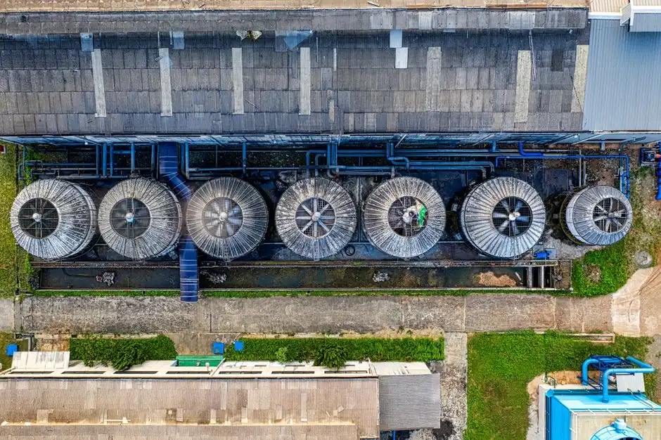
The first commercial CASS installations were in the United States: the Prairie wastewater-treatment plant in Minnesota, the Toledo wastewater-treatment plant in Ohio, and a district wastewater-treatment plant in Michigan. All reported CODCr removal up to 85% and BOD5 removal up to 95%, with good nitrogen and phosphorus removal (source: sinokle.com). The technology then spread through dozens of engineering examples in China for industrial and domestic sewage in Shanghai, Kunming, and Beijing (source: sinokle.com).
In 2026, CASS is most often specified for the 1,000–50,000 m³/day duty envelope — package plants for residential communities, hospitals, hotels, and small industrial estates. That includes underground Underground Package Sewage Treatment Plant (WSZ Series) configurations where the absence of a separate clarifier and the compact tank geometry are decisive. For flows above ~50,000 m³/day, multiple CASS modules in parallel keep decanter hydraulics manageable and maintain redundancy during maintenance. Comparable cyclic alternatives include the AAO Process Working Principle: 2026 Engineering Guide to Anaerobic-Anoxic-Oxic Biology. Also evaluate continuous-flow Oxidation Ditch Design Parameters: 2026 Engineering Reference where nutrient targets or operator skill favor those layouts.
Common CASS Design and Operation Pitfalls
Four failure modes account for the majority of underperforming CASS installations seen in commissioning reviews, and each has a known preventive measure:
- Selector zone too small — under 5% of total volume, the F/M gradient collapses, filaments outcompete floc-formers, and the main zone loses settleability. Fix: hold the selector at 5–15% of total volume, with DO held below 0.5 mg/L.
- Decanter submerged during react or settle — a stuck or mis-calibrated decanter allows short-circuiting and pushes sludge into the effluent. Fix: hardwire the decanter travel into the phase controller, and verify with a manual lockout test every quarter.
- Microporous diffusers in the selector — fine-bubble membranes foul within months under high-F/M selector duty. Fix: coarse-bubble or self-sealing rubber discs in the selector; reserve fine-bubble for the main reaction zone.
- Influent peak flow exceeding the main zone buffer — sustained peaks push sludge into the decanter and drag TSS over the discharge limit. Fix: provide upstream flow equalization or size the idle phase to absorb the expected peak-to-average ratio.
Selection checklist before you freeze the process memo:
- Confirm selector volume is 5–15% of total reactor volume with DO <0.5 mg/L in anoxic fill.
- Set main-zone DO at 2.0–3.0 mg/L and MLSS at 2,500–5,000 mg/L for the design load.
- Decouple SRT (10–25 d) from cycle length; use idle only for diurnal buffering.
- Specify coarse-bubble or mechanical aeration in the selector; fine-bubble in the main zone.
- Interlock the liftable decanter so it cannot lower during react or settle.
- Size for 1,000–50,000 m³/day per module, or parallel modules above that band.
- Track SV30; treat a climb from ~100 mL/g toward 200 mL/g as a selector alarm.
For a deeper operator-side checklist on maintaining compact package plants in this duty envelope, see the Compact Sewage Treatment Unit Maintenance Guide: Industrial Protocols.
Who This Is For / Who Should Look Elsewhere / Next Step
This guide is for plant engineers, EPC process leads, and procurement managers sizing continuous-feed SBR variants in the 1,000–50,000 m³/day band who need selector, cycle, and aeration rules they can put in a memo. Look elsewhere if you need membrane bioreactor effluent quality as the primary driver, or if your flow sheet already commits to continuous secondary clarification rather than in-tank decanting. For a duty-matched package layout, send influent COD/BOD, peak-to-average ratio, and discharge limits through our CASS process working principle inquiry form. We will check reactor volume and decanter duty against your load.
Frequently Asked Questions
What is the CASS process in wastewater treatment?
The CASS (Cyclic Activated Sludge System) process is a continuously fed, intermittently decanted SBR variant. One tank is split into a biological selector zone and a main reaction zone, and the reactor cycles through fill, react, settle, decant, and idle phases. A liftable decanter replaces the secondary clarifier. Continuous influent enters through the selector while the main zone still settles and decants in batch sequence.
How does the CASS process differ from SBR?
Classical SBR is batch-fed per cycle and usually needs an upstream equalization basin. CASS is continuously fed through a dedicated selector zone that buffers shock loads and protects the settle step. CASS also uses a liftable decanter and operates without a separate clarifier or sludge-return pumping station, which is why it fits continuous municipal and industrial service more cleanly than strict batch SBR.
What does the biological selector zone do in CASS?
The selector runs at a high F/M ratio under anoxic or low-DO conditions. That kinetic setting selects floc-forming bacteria over filamentous organisms and suppresses bulking in the main reaction zone. It is sized at 5–15% of total reactor volume so the F/M gradient holds. When selector volume or DO drifts, SV30 usually rises first and settleability follows.
What is typical CODCr and BOD5 removal in CASS?
Reference U.S. plants — Prairie MN, Toledo OH, and a Michigan district plant — report CODCr removal up to 85% and BOD5 removal up to 95%, with good nitrogen and phosphorus removal (source: sinokle.com). These figures are conditional on operating within the DO, MLSS, F/M, SRT, and HRT ranges given in the parameter table above. Treat them as an upper envelope, not a guarantee for every influent.
Does CASS need a secondary clarifier?
No. The settle and decant phases occur in the same reactor vessel. The liftable decanter draws clarified supernatant from below the scum layer, so a separate secondary clarifier and external sludge-return line are not required (source: sinokle.com). That is the main reason CASS footprints run about 20–30% smaller than conventional continuous-flow CAS at equal capacity.