
Why Petroleum Wastewater in Little Rock Forces the DAF-vs-Clarifier Question in 2026
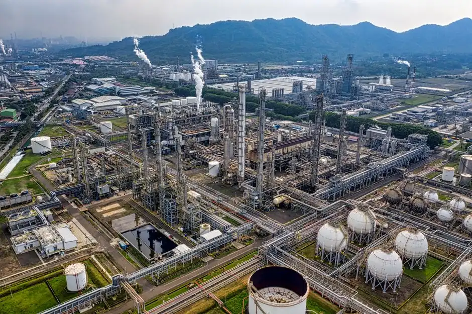
Petroleum-handling facilities across the Little Rock corridor — fuel terminals along the Arkansas River, lube-oil blenders in Pulaski County, refineries in El Dorado, and metalworking shops running hydrocarbon coolants — discharge a wastewater profile that gravity separation was never designed to finish. The 2026 operating reality is tighter: Arkansas DEQ and the regional POTWs are sampling more often, the daily-maximum oil & grease limit at most pretreatment programs sits at 100 mg/L, and a single visible sheen event now triggers a noncompliance flag. Influent FOG on these streams commonly lands between 150 and 800 mg/L with a meaningful fraction already emulsified below 150 microns by cleaners, coolants, and surfactants, so the separator that worked in 2006 often fails in 2026. That gap is why the DAF-or-clarifier decision has moved from a design preference to a CAPEX gate, and why the default answer for most petroleum streams in central Arkansas now points to a dissolved air flotation (DAF) system rather than another round of lamella plates.
How a Clarifier Separates Oil and Solids (and Where It Stops Working)
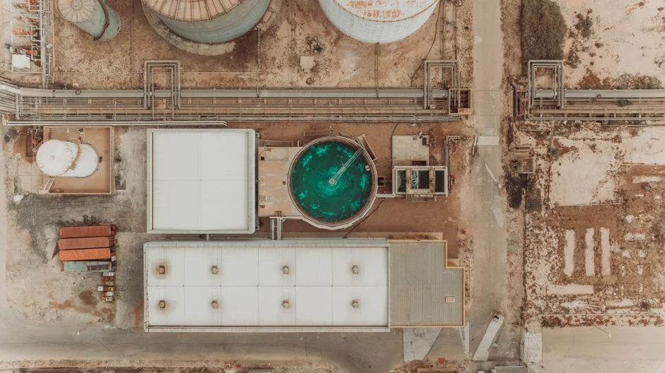
A conventional gravity clarifier — whether a concrete basin, a steel tank, or a high-rate lamella unit such as a HydropureWater lamella clarifier — relies on Stokes-law settling: quiescent residence time, lamella plates to shorten the effective settling path, a sludge hopper for settled solids, and a surface scum baffle for free oil. It is an effective device for grit, settleable TSS above roughly 50–100 microns, and large free-oil droplets above approximately 150 microns. The problem is that petroleum wastewater from refineries, terminals, and metalworking rarely presents in that form. Free oil above 150 microns is usually skimmed by an upstream API separator, and what reaches the clarifier is dominated by emulsified droplets in the 10–80 micron range — droplets whose Stokes rise velocity is on the order of 0.1–1.0 m/h, far below what a 1–2 hour clarifier retention time can deliver. Surfactants from parts cleaners, coolants, and alkaline degreasers further stabilize that emulsion, so the clarifier discharges a sheen, the POTW pulls a daily-max exceedance, and the cycle repeats. In practice, clarifiers on petroleum streams typically deliver 40–60% FOG removal when sized for hydraulic load and 20–35% once the feed turns emulsified — not enough to meet a 100 mg/L daily max on a 500 mg/L feed.
How a DAF System Actually Treats Petroleum Wastewater
A dissolved air flotation unit works by saturating a recycle stream with air at 60–90 psig, then releasing that pressure inside a flotation tank where the dissolved air comes out of solution as 30–50 micron microbubbles (per SigmaDAF / Clearwater Industries technical documentation). Those bubbles attach to oil droplets and to chemically flocculated solids, lowering the effective density below water and lifting the mixture to the surface in 3–5 minutes, where a paddle skimmer removes the float layer. The mechanism is the opposite of a clarifier: instead of waiting for heavy material to fall, DAF actively floats light and emulsified material that gravity cannot resolve. This is why DAF is the technology of choice for oil and gas applications — it separates low-density particles and emulsified oils that are difficult to settle, making it standard for produced water, refinery wastewater, and fracturing flowback (per Ecologix Environmental Systems). In a refinery, the DAF can serve as either primary or secondary treatment, cutting oil & grease and TSS load before biological polishing or direct NPDES discharge. Performance is unlocked upstream by coagulation and flocculation chemistry: a coagulant (typically PAC, ferric chloride, or alum at 50–200 mg/L) neutralizes charge, then a flocculant (anionic or cationic polyacrylamide at 1–10 mg/L) grows a 200–500 micron floc that the microbubbles can nucleate onto. Without that chemical conditioning, the DAF is just an air-stripped tank; with it, FOG removals of 85–95% and TSS removals of 70–90% are routine on refinery and metalworking feeds.
DAF vs Clarifier for Petroleum Streams: Side-by-Side Comparison
The matrix below serves as a reference for procurement and process engineering to evaluate technologies against a typical Little Rock petroleum feed.
| Decision axis | Conventional gravity / lamella clarifier | Dissolved air flotation (DAF) |
|---|---|---|
| Target contaminant | Free oil > ~150 µm, settleable TSS > ~50 µm, grit | Free oil, emulsified oil down to 10–30 µm, FOG, TSS, light floc |
| Typical FOG removal on petroleum feed | 20–60% | 85–95% (with coagulation/flocculation) |
| Typical TSS removal on refinery / metalworking feed | 40–70% | 70–90% |
| Mechanism floor (droplet size handled) | ~150 µm free oil; ineffective on emulsified oil | ~10–30 µm emulsified oil via 30–50 µm microbubbles |
| Hydraulic retention time | 1.5–3.0 h | 15–30 min (contact zone) + 5–10 min float zone |
| Footprint for 50–150 GPM | Large concrete basin or tall lamella; high civil cost | Compact packaged skid; ~10–25% of clarifier footprint |
| CAPEX band (equipment, ex-installation) | Lower for carbon-steel basin; rises sharply with stainless or concrete | Higher unit cost; lower total installed cost when land and civil are constrained |
| OPEX drivers | Sludge hauling, basin cleaning, minimal chemistry | Compressed air (blower ~5–15 kW), polymer/coagulant $0.005–$0.02 per gallon, sludge hauling |
| Sensitivity to flow surges | High — short-circuits skim layer, resuspends sludge | Moderate — equalization upstream recommended |
| Best-fit petroleum use case (per Ecologix oil & gas scope) | Heavy grit, produced-water desand, sludge thickening | Produced water, refinery primary/secondary treatment, fracturing flowback, lube blending, metalworking coolant |
The decision rule is clear: if the stream carries FOG above approximately 200 mg/L, or any measurable emulsified oil below 100 microns, the clarifier column cannot meet a 100 mg/L daily-max discharge limit without a polishing step. Choose the clarifier only when the stream is dominated by settleable grit and heavy TSS with low FOG, which is unusual in a Little Rock petroleum context.
Matching the Technology to Your Little Rock Site Conditions
Four facility archetypes drive most of the 2026 inquiry volume in central Arkansas. (1) Refineries and large fuel terminals discharging to a POTW should specify a DAF with coagulation/flocculation as primary treatment, sized to handle the peak hourly flow from storm-water contact and tank draw-off; the existing API separator stays in place as pre-treatment, and any older clarifier can be repurposed as a sludge thickener or equalization basin. (2) Lube-oil blending operations typically see 200–600 mg/L FOG with a high emulsified fraction from additive packages — DAF is the default, paired with pH adjustment to 6.5–7.5 and a cationic flocculant. (3) Metalworking shops running hydrocarbon coolants are the most common undersized-clarifier failure mode: coolant stabilizes 5–40 micron oil droplets, the clarifier skims nothing, and the POTW flags a sheen — a DAF preceded by a coagulant dose and a HydropureWater automatic chemical dosing system reliably drops O&G from 300–1,000 mg/L to under 50 mg/L. (4) Food or rendering plants with incidental petroleum contamination are the one case where a lamella clarifier may suffice as primary treatment with a small DAF as a polishing step, because the bulk of the load is settleable FOG and proteinaceous solids, not emulsified oil. Across all four, the existing clarifier is rarely scrapped — it is repurposed as a thickener or EQ basin, which materially softens the 2026 CAPEX conversation.
2026 Equipment, Footprint, and Cost Considerations for Little Rock Factories
Packaged DAF skids for industrial flow rates are now a mature, modular product category. Standard DAF models cover a wide range of flowrates, with compact pre-assembled turnkey skids handling flows of 66 GPM or less in a single skid and modular two-skid designs for larger flows (per Clearwater Industries / SigmaDAF, 2026). For a typical Little Rock facility in the 25–150 GPM range, a packaged DAF with chemical conditioning, PLC, and skimmer fits inside a 20–40 ft enclosure, compared to a clarifier basin that needs 200–500 sq ft of civil footprint plus concrete work. CAPEX varies materially with material of construction — 304 stainless is the default, 316 stainless or polypropylene is available for higher-chloride or higher-temperature petroleum streams — and with tank volume, skimmer horsepower, and whether the skid ships pre-assembled or modular. OPEX is dominated by compressed-air energy (typically 5–15 kW on a 50–100 GPM unit), polymer and coagulant consumption, and sludge hauling; on a per-gallon-treated basis, DAF and clarifier OPEX are often within 20–30% of each other, but DAF wins on total installed cost when land, civil, and structural steel are constrained. Validate final numbers with a vendor survey and a bench- or pilot-scale jar test on actual plant wastewater; every petroleum stream behaves differently, and the jar test is the most effective way to verify performance for a 2026 CAPEX decision.
Frequently Asked Questions
What influent FOG concentration forces a DAF over a clarifier for petroleum wastewater?
Once FOG exceeds approximately 200 mg/L, or any measurable fraction sits below 100 microns as emulsified oil, a conventional clarifier cannot reliably meet a 100 mg/L daily-max oil & grease limit and a DAF becomes the correct primary separator (per SigmaDAF technical data and Arkansas DEQ pretreatment norms).
Why does a DAF remove emulsified oil that a clarifier cannot?
DAF generates 30–50 micron microbubbles that attach to oil droplets and chemically flocculated solids and float them in 3–5 minutes, whereas a clarifier depends on Stokes-law settling and only effectively captures free oil above roughly 150 microns, leaving emulsified droplets in the discharge (per Clearwater Industries / SigmaDAF, 2026).
Can a DAF and a clarifier be combined, and does the existing clarifier have to be scrapped?
Yes, and no. A common 2026 retrofit keeps the existing clarifier as a sludge thickener or equalization basin ahead of a new DAF, which lowers total CAPEX and stabilizes flow surges before the flotation unit.
What is the typical flow range for a packaged DAF skid suitable for a Little Rock facility?
Compact pre-assembled DAF skids handle flows of 66 GPM or less in a single skid, and modular two-skid systems cover larger flows, with standard DAF models spanning a wide range of industrial flowrates (per Clearwater Industries / SigmaDAF, 2026).