Why Dubai Data Centers Need a Different Water Strategy
A 100 MW data center in a temperate climate can demand up to 2 million liters of water per day for cooling (IDE, 2026); the same IT load in Dubai, operating at 8–10 cycles of concentration (CoC) to keep fresh-water draw low, still pulls roughly 800,000–1,000,000 L/day of cooling makeup into a 50 MW hyperscale site. The Gulf operating envelope inverts the usual water-economics argument: it is not about finding more water, it is about refusing to spend energy, capital, and political capital to desalinate and pipe each additional cubic meter. DEWA's desalinated supply is capacity-constrained, energy-intensive, and tariffed to discourage waste, which means freshwater minimization is a project-finance constraint, not a sustainability add-on. Anything that raises the cooling tower's sustainable CoC without tripping scale or biological fouling directly reduces DEWA draw, sewer discharge, and the embodied carbon of every liter consumed.
Climate is the multiplier. Dubai's summer wet-bulb sits near 45°C, and dry-bulb regularly exceeds that during peak grid stress when AI inference loads peak in parallel with air-conditioning demand. Higher wet-bulb raises evaporative loss per MWh of heat rejected, and any fixed-volume blowdown target therefore requires more makeup than a temperate U.S. baseline would suggest. As a rough mechanism, the same IT load sheds more liters per hour of evaporation in Dubai than in Frankfurt or Phoenix-on-a-mild-day, so blowdown volume per MW runs 30–60% higher in the Gulf even before the operator chooses to push CoC. IDE flags that AI compute density is the load-growth driver through 2026 and beyond (IDE, 2026), and that makes cooling-tower-blowdown (CTBD) reuse a baseline permitting and project-finance requirement for any new build, not an optional sustainability module.
What Dubai Cooling Tower Blowdown Actually Contains
CTBD is the concentrated purge from an evaporative cooling loop: as pure water leaves as vapor, the dissolved salts and treatment chemicals stay behind, so the purge carries everything that was not volatile (IDE, 2026; Water Utility Report, 2026-04). For a Gulf site blending DEWA desalinated supply with a brackish sidestream — common where once-through heat rejection or hybrid cooling touches groundwater or Gulf seawater — the typical CTBD envelope looks like the table below. Exact numbers depend on site-specific blending ratios, which is why every design basis in Dubai should begin with a 30-day influent characterization campaign rather than borrowed U.S. numbers.
| Parameter | Typical Dubai CTBD range (8–10 CoC) | Design implication |
|---|---|---|
| TDS | 2,000–6,000 mg/L | Sets RO feed osmotic pressure; pushes energy per m³ of permeate |
| Silica (SiO₂) | 40–120 mg/L | Primary scaling ceiling for high-recovery RO; needs pretreatment or controlled precipitation |
| Calcium hardness (as CaCO₃) | 600–1,500 mg/L | Drives CaCO₃ and CaSO₄ scaling; targeted by softening and antiscalant |
| Alkalinity (as CaCO₃) | 200–600 mg/L | Sets Langelier Saturation Index; controls acid feed for pH stabilization |
| Chloride | 500–2,000 mg/L | Corrosion driver for stainless and mild-steel components; sets material selection |
| Residual biocides and phosphonates | Site-specific, typically 1–20 mg/L active | Defines biocide-rotation strategy and pretreatment to protect RO membranes |
A February 2026 TNFD case study cited by Water Utility Report notes that evaporative cooling wastewater can carry high concentrations of salts, heavy metals, and other pollutants when mismanaged — the point being that "water-efficient" claims on intake do not address water quality on the discharge side. The chemistry matters because at 8 CoC the dissolved solids concentrate roughly 8× relative to makeup, which is exactly where conventional phosphonate and dispersant scale-inhibition collapses; above 6 CoC, the literature (Genesis Water Technologies, 2026) and field experience show that aggressive chemical rotation can eliminate the very savings it is meant to unlock. Dubai's 8–10 CoC operating point therefore requires a physical-plus-membrane treatment train, not just a stronger chemical cocktail.
UAE Regulatory Baseline for Data Center Discharge
UAE Federal Decree-Law No. 12 of 2018 on the Integrated Management of Waste is the federal anchor, and Dubai Municipality environmental discharge permits set the site-specific effluent limits for any discharge to sewer or sea outfall. For a data center, the pinch points are predictable: total dissolved solids (TDS), temperature (cooling-tower return can violate thermal limits if not tempered), residual oxidizing biocide (chlorine and bromine species), pH, and heavy metals if process wastewater from battery rooms, boiler blowdown, or humidification reject is co-mingled with the CTBD stream.
Reuse does not eliminate compliance. The TNFD case study and a 2026 PLOS Water paper on datacenter-driven water insecurity (cited in Water Utility Report, 2026-04) both underline that recycled water changes the chemistry challenge rather than removing it; even a hyperscaler running zero-liquid-discharge (ZLD) still produces a solid salt or brine waste stream that falls under Dubai Municipality solid-waste rules. Documentation discipline has become a lender and investor concern: TNFD and PLOS Water now appear in environmental, social, and governance due-diligence questionnaires, so the engineering basis of record — the influent characterization, the mass balance, the discharge permit, the contingency plan for brine handling — needs to read like an audit document, not a marketing brief.
The 2026 Process Train for Dubai Data Centers
The defensible process train for a Dubai hyperscaler runs three stages, with a fourth scale-down option for colocation sites. The parameter table below is the technical centerpiece; the narrative below it walks the engineer through what each stage is doing and why.
| Stage | Process | Key parameters | Output |
|---|---|---|---|
| 1 — Sidestream pretreatment | Self-cleaning multi-media filter → dissolved air flotation pre-filter for cooling tower blowdown → side-stream softening | 5–10× reduction in suspended solids; calcium and silica drop to RO-friendly levels | Clarified water to RO feed |
| 2 — High-recovery RO with controlled salt precipitation | High-recovery industrial RO system at 70–80% local recovery, alternating production and high-velocity flush; concentrate to fluidized-bed reactor where inhibitors are deactivated and sparingly soluble salts precipitate as dense pellets | Permeate silica ~1 mg/L at 95% overall recovery; induction-phase operation holds scaling below threshold (IDE, 2026) | Recycled permeate for cooling-tower makeup; pelletized solids for waste handling |
| 3 — Brine management / ZLD | Thermal or mechanical crystallizer on clarified NaCl brine; or controlled disposal under Dubai Municipality permit | Brine volume cut to match the disposal pathway's permitted capacity | ZLD solid or permitted brine discharge |
| 4 — Scale-down (5–15 MW colocation) | Multi-media filter for CTBD pretreatment → RO → municipal sewer within TDS limits; biocide rotation handled by an on-site chlorine dioxide generator for cooling loop microbial control | 60–80% CTBD recovery; no crystallizer (Genesis Water Technologies, 2026) | Recovered water to cooling tower; concentrate to sewer |
Stage 1 is where most Gulf projects get the chemistry wrong if they copy a U.S. template. A self-cleaning multi-media filter for CTBD pretreatment drops the suspended load, a dissolved air flotation pre-filter for cooling tower blowdown removes oils and lighter solids that would otherwise foul membranes, and side-stream softening targets calcium and silica before they reach the RO. Stage 2 applies the IDE MAXH₂O logic: operate the brackish RO at a conservative local recovery safely below scaling limits, then route concentrate to a fluidized-bed reactor where scaling inhibitors are deactivated and silica, calcium carbonate, and other sparingly soluble salts precipitate as dense pellets (IDE, 2026). The dynamic RO mode — alternating short production and high-velocity flush — holds operation inside the induction phase of crystallization, so supersaturation exists but crystals have not yet formed. The result is stable operation well past the conventional 75–80% ceiling, with permeate silica around 1 mg/L at 95% overall recovery. Stage 3 is a permitting and cost decision: clarified brine (now mostly NaCl) goes to a thermal or mechanical crystallizer for ZLD, or to a controlled disposal pathway under Dubai Municipality permit. For a 5–15 MW colocation site, the modular physical-separation-plus-RO approach delivers 60–80% CTBD recovery without the capital and operating burden of a crystallizer (Genesis Water Technologies, 2026).
Cycles of Concentration, Recovery, and the Real Water Math
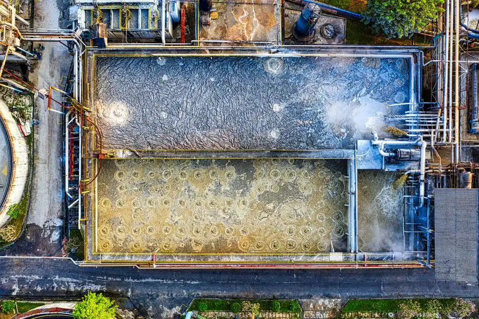
The most common engineering miscalculation in CTBD projects is reading a CoC change as a percent improvement when it is a percentage-point improvement in blowdown ratio. The math is the standard blowdown fraction 1/(CoC − 1): at 4 CoC the blowdown is 25% of makeup, at 6 CoC it is 20%, at 8 CoC roughly 14%, and at 10 CoC about 11% (Genesis Water Technologies, 2026, extended to the Dubai operating range). The move from 4 to 6 CoC is therefore a 5-percentage-point blowdown reduction, or a 20% relative improvement, not the 50% that often ends up in board slides.
In absolute terms the case still holds. At a 50 MW Dubai site pulling 900,000 L/day of makeup, the difference between 4 and 8 CoC is about 100,000 L/day of avoided makeup and avoided discharge — every day, every year — and the difference between 60% and 90% overall water recovery in a treatment train is effectively a 4–6 point lift in sustainable CoC without the chemical and biological risk that pushes operators back down to 5–6 CoC in the first place. That is the right way to present the math to a Dubai project team: not "we will save half your blowdown," but "we will raise your sustainable CoC from 5 to 8–10 and recover 135,000–180,000 L/day that you are currently paying to import and discharge."
Equipment Sizing, Costs, and Payback in the Gulf
For a baseline 50 MW Dubai site, cooling demand is roughly 800,000–1,000,000 L/day, which at 6 CoC produces about 150,000–200,000 L/day of CTBD; a 90%-recovery treatment train therefore yields on the order of 135,000–180,000 L/day of recycled water. The reference point from Genesis Water Technologies (2026) is a 15 MW U.S. site at $200,000 of capital for 60% CTBD recovery, returning a 3–5 year simple payback once avoided discharge, water, and energy costs are included; in the Gulf, freshwater and discharge tariffs are higher, ambient temperature is higher, and the avoided-cost stack is therefore steeper, so a defensible payback envelope for a Dubai 50 MW hyperscale site is at or below that 3–5 year band even after Gulf-specific CAPEX uplift.
Two Gulf-specific cost drivers are worth flagging in any design review. First, higher ambient temperature increases crystallizer energy use per cubic meter of brine processed, so a ZLD block in Dubai carries a higher OPEX per m³ of water recovered than a temperate-U.S. equivalent. Second, higher TDS in makeup increases RO membrane area per m³ of permeate, so the high-recovery membrane stage needs more square meters than a U.S. design at the same flow. The avoided-cost categories to put on the table with finance are: DEWA freshwater purchase, Dubai Municipality sewer discharge fees, biocide and chemical cost reduction from operating at higher CoC, and avoided infrastructure for new freshwater supply. An automatic chemical dosing system for antiscalant and pH control protects the membrane stage and tightens chemical cost, and a filter press for dewatering the fluidized-bed pellets turns the salt-precipitation waste stream into a handleable solid. For related Gulf and tropical project templates, see the Dammam data center cooling blowdown treatment guide, the data center cooling blowdown treatment in Port Harcourt reference, and the Kuala Lumpur data center cooling blowdown treatment guide.
Frequently Asked Questions
What is the realistic water recovery rate for a Dubai data center's cooling blowdown?
A well-designed Dubai hyperscale site running 8–10 CoC with a high-recovery RO plus controlled salt precipitation can reach about 90–95% overall water recovery, with permeate silica around 1 mg/L (IDE, 2026). Smaller 5–15 MW colocation sites using a modular physical-separation-plus-RO train typically achieve 60–80% recovery without a crystallizer (Genesis Water Technologies, 2026).
Why does conventional reverse osmosis stop at 75–80% recovery on cooling tower blowdown?
Conventional brackish-water RO is capped by the scaling thresholds of sparingly soluble salts — silica, calcium carbonate, and calcium sulfate — which concentrate on the membrane surface as recovery rises. Beyond 75–80% local recovery, scaling risk, chemical demand, and cleaning frequency climb faster than permeate output (IDE, 2026). High-recovery designs work around this ceiling by deactivating inhibitors and precipitating the problematic salts as pellets in a fluidized-bed reactor before the concentrate ever reaches a disposal pathway.
Which UAE regulations govern data center wastewater discharge in Dubai?
UAE Federal Decree-Law No. 12 of 2018 on the Integrated Management of Waste is the federal anchor, and Dubai Municipality environmental discharge permits set site-specific effluent limits for sewer or sea-outfall discharge. Typical pinch points are TDS, temperature, residual oxidizing biocide, pH, and heavy metals where process wastewater is co-mingled with the CTBD stream.
Can a 5–10 MW colocation facility in Dubai afford high-recovery CTBD treatment, or is it only for hyperscale?
Modular physical-separation-plus-RO systems sized to colocation flows deliver 60–80% CTBD recovery without the CAPEX and specialized staffing of a hyperscale ZLD block (Genesis Water Technologies, 2026). Capital cost per gallon treated is higher than at hyperscale, but the modular scope keeps the payback inside the typical 3–5 year window once DEWA water, sewer discharge, and chemical costs are included.
How does Gulf summer temperature change the blowdown math compared to U.S. or European sites?
A 45°C summer wet-bulb lifts evaporative loss per MWh of heat rejected well above temperate-U.S. baselines, which raises blowdown volume per MW by roughly 30–60% for the same IT load and the same CoC target. That is the mechanism, not a quoted Gulf multiplier: higher wet-bulb simply means more makeup per MWh, so any CoC and recovery gain translates into larger absolute liter savings than the same percentage improvement would yield in Frankfurt or the U.S. Pacific Northwest.