
Why Semiconductor Wastewater Is a Different Selection Problem
Semiconductor fab wastewater combines two contaminant fractions that almost never appear together in food, dairy, or metal-finishing operations, and that combination is exactly what breaks generic DAF-versus-clarifier heuristics. The first fraction is buoyant organics: photoresist polymer, TMAH (tetramethylammonium hydroxide) developer, fluorinated surfactants from wet-etch baths, and trace solvents — all near SG 0.95–1.02, all emulsified, all prone to foaming. The second fraction is dense inorganic CMP slurry: fumed or colloidal silica (SiO2), ceria (CeO2), and alumina (Al2O3) at SG 2.0–4.0, often 50–300 nm primary particle size, with surface charge that resists bubble attachment unless coagulant chemistry is tuned. A working fab generates both within the same shift, and the two fractions interact: photoresist coats slurry particles and changes their effective buoyancy, while slurry particles adsorb developer and carry it into the clarifier underflow.
Generic industrial benchmarks translate only partially. DAF hits 92–97% TSS removal and up to 95% FOG removal in food and dairy service (HydropureWater field data, 2025), but those numbers assume a buoyant, low-TSS, low-density feed. CMP oxide slurry at 500–2,000 mg/L TSS behaves more like a mineral slurry than a FOG stream, and forces polymer demand up by 3–5× to get bubble attachment. Conversely, a gravity clarifier that handles 90% of settled TSS in a mineral processing plant will discharge 40–60% of incoming photoresist over the weir, because photoresist floc has essentially neutral buoyancy and will not sink at any reasonable retention time.
Stuart-area fabs discharging to Martin County Utilities or under FDEP surface-water permits must meet the numerical limits in FDEP Chapter 62-625, with TSS typically capped at 30 mg/L monthly average and FOG, fluoride, copper, and lead at categorical standards that vary by discharge route. The separator choice is downstream of, not a substitute for, fluoride adjustment, metals precipitation, and any required RO polishing — but it determines whether the upstream chemistry has to do extra work to hit those limits. That is why the central question for a 2026 spec is not "DAF or clarifier" but "which separator, for which stream, in what sequence."
DAF vs Gravity Clarifier: How Each Separator Actually Works
A DAF unit pushes 10–30% of clarified effluent through a pressurization loop at 4–6 bar, saturates it with air at 85–95% efficiency, then releases the pressure at the flotation tank inlet. The drop in pressure precipitates 20–100 μm micro-bubbles that attach to conditioned floc and lift it to the surface in 20–30 minutes of retention. A mechanical skimmer scrapes the 3–5% solids float into a trough; heavier particles that cannot be lifted settle to a bottom auger. The physics works best when the target particle is already near SG 1.0 and has been flocculated with a charge-matched polymer at 0.5–5 mg/L.
A conventional or lamella clarifier does the opposite. It is a passive vessel in which particles with SG measurably greater than 1.0 settle over 2–4 hours of retention. A lamella clarifier stacks 60° inclined plates at 50–80 mm spacing, shortening the effective settling path and pushing surface loading rates to 20–40 m/h — roughly 2–4× a conventional clarifier's 5–10 m/h. Clarifier underflow is typically 1–2% solids, which is 50–70% more volume to haul than DAF float for the same dry solids mass.
Energy and footprint invert the conventional cost intuition. DAF uses 0.2–0.5 kWh/m³ for the recycle pump and air compressor but treats the same flow in 20–25% of the footprint. A clarifier uses almost no operational energy, yet needs 5× the footprint to match DAF hydraulic capacity, and a much higher polymer dose if the stream contains any buoyant fraction. Standard builds are 304SS, with 316SS or polypropylene available for high-fluoride or high-TMAH service (clearwaterind.com, 2026-04). For a fab, where clean-room adjacency makes every square meter expensive, the footprint trade is often decisive. The DAF system and the high-efficiency lamella clarifier are the two unit operations being compared.
| Parameter | DAF | Lamella Clarifier | Conventional Clarifier |
|---|---|---|---|
| Hydraulic retention | 20–30 min | 45–90 min | 2–4 h |
| Surface loading | 5–15 m/h | 20–40 m/h | 5–10 m/h |
| Micro-bubble size | 20–100 μm | n/a | n/a |
| Saturation pressure | 4–6 bar | n/a | n/a |
| Recycle ratio | 10–30% | none | none |
| Polymer demand | 0.5–5 mg/L | 2–15 mg/L (for mixed streams) | 2–20 mg/L |
| Sludge solids | 3–5% float | 1–2% underflow | 1–2% underflow |
| Footprint at 50 m³/h | ~8–10 m² | ~20–25 m² | ~80–120 m² |
| Energy use | 0.2–0.5 kWh/m³ | <0.05 kWh/m³ | <0.05 kWh/m³ |
| Best target fraction | Buoyant organics, FOG, emulsions | Dense inorganics, settleable TSS | Coarse settleables, grit |
The Semiconductor Decision Matrix: Which Separator for Which Stream
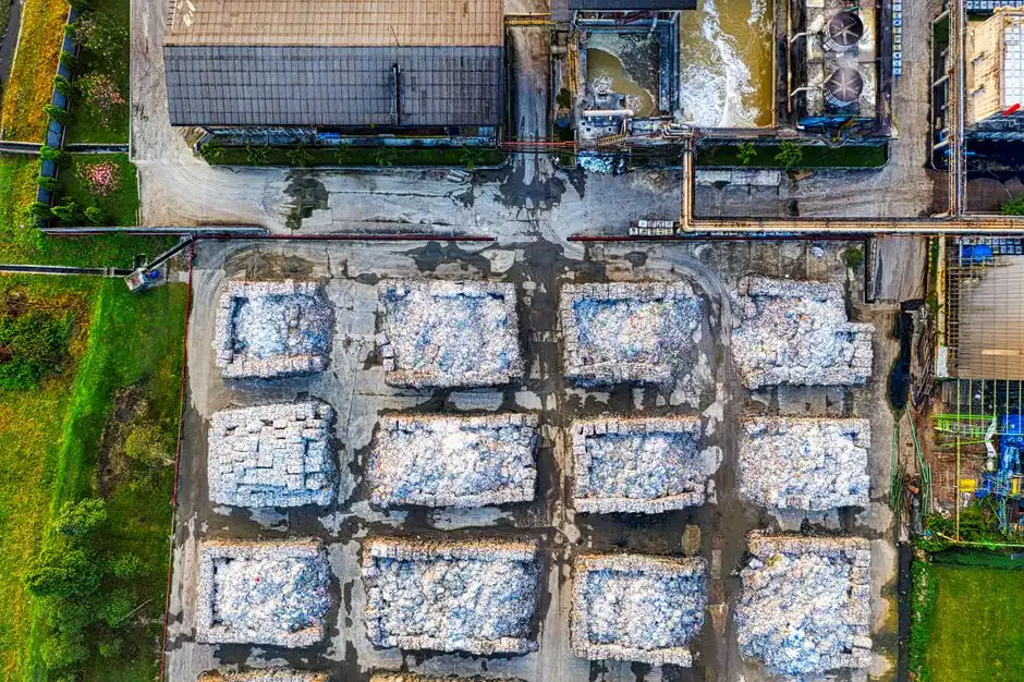
The matrix below scores five real fab stream types against four selection criteria on a 1–5 scale, where 5 is the best fit. Scores reflect the physics of bubble attachment versus gravity settling, not vendor preference. Each row should be read as "for this stream, this unit operation scores X out of 5 on this criterion."
| Fab Stream | Dominant Fraction | DAF Score (1–5) | Lamella Clarifier Score (1–5) | Winner |
|---|---|---|---|---|
| CMP oxide slurry (SiO2) | Dense, 50–200 nm, SG 2.2 | 2 (high polymer to float) | 5 (settles readily) | Lamella |
| CMP metal slurry (CeO2, Al2O3) | Dense, abrasive, SG 4.0+ | 2 (coating/charge issues) | 4 (settles; abrasive wear concern) | Lamella |
| Photoresist & developer | Buoyant polymer + TMAH, SG ~1.0 | 5 (bubbles attach easily) | 1 (will not settle in retention window) | DAF |
| Wet-etch rinse (HF, NH4F) | Fluoride + trace organics, low TSS | 4 (lifts organics; F⁻ needs separate removal) | 2 (low TSS; mostly chemical step) | DAF (for organics); F⁻ by Ca precipitation |
| Scrubber blowdown (mixed) | Variable: slurry carryover + organics | 3 (handles organics; struggles on slurry alone) | 3 (handles slurry; misses photoresist) | Hybrid required |
| Weighted winner | Mixed fab effluent | 3.2 | 3.0 | Hybrid: DAF upstream, Lamella downstream |
The takeaway: no single unit operation wins all five rows. CMP streams lean toward lamella because their particles are 2–4× the density of water and do not need active aeration to drop out. Photoresist and developer streams lean toward DAF because their floc has effectively neutral buoyancy and would never reach the underflow in a clarifier's retention window. Scrubber blowdown and any real fab composite stream — where slurry carryover and resist loading arrive in the same batch — score 3/3 and must be handled as a hybrid train. The chemistry matters: DAF on raw oxide slurry without charge-matched cationic polymer will produce cloudy sub-100 mg/L effluent, while a clarifier on raw photoresist will discharge visible solids over the weir no matter how much anionic polymer is added.
The 2026 Hybrid Train: DAF Upstream, Lamella Downstream
The defensible 2026 answer for any fab with mixed buoyant-plus-dense loading is a sequenced train, not a single unit operation. The process flow is: equalization → pH and fluoride adjustment (typically Ca-based precipitation targeting F⁻ < 10 mg/L before further treatment) → DAF upstream to lift photoresist, TMAH-bound organics, fluorosurfactant residues, and FOG → lamella clarifier downstream to settle residual CMP slurry, metal hydroxides, and any particles that escaped flotation → fluoride/metal polishing (often calcium or membrane) → RO or direct discharge under FDEP permit conditions.
The order is not arbitrary. Putting DAF first removes the buoyant fraction that would otherwise coat lamella plates, blind them with floating scum, and consume polymer that the clarifier needs for slurry coagulation. Putting lamella second catches what DAF cannot float: dense slurry particles that passed through under the bubble curtain, plus precipitates from the upstream pH/F⁻ step. Field installations consistently report 80–90% overall TSS removal across the train, with the lamella effluent stable at 15–30 mg/L TSS, which is at or below the FDEP Chapter 62-625 monthly average for many surface-water discharge routes.
Footprint math drives spec decisions in fabs. A hybrid train sized for 4–50 m³/h — a common range for a single tool farm or a sub-fab collection sump — fits in roughly 25–30 m², versus 80–120 m² for a clarifier-only system at the same flow. Inside a fab where structural and clean-room adjacency costs run $3,000–$8,000 per m², that footprint delta is often the single largest line item in the CAPEX comparison. Polymer chemistry should be split: cationic polyacrylamide (typically 0.5–3 mg/L) for the DAF stage to flocculate negatively charged photoresist, and either anionic polymer or a dual-polymer scheme (cationic + anionic) for the lamella stage to capture oxide and metal-oxide slurry. Jar testing on site-specific influent is mandatory before vendor selection — generic dose curves will miss the interaction between TMAH, fluoride, and slurry surface charge. The automatic polymer dosing skid is the practical way to hold those two dose curves steady across shift-to-shift TSS swings. A full semiconductor pretreatment compliance guide walks through the upstream chemistry and discharge-numerical-limit logic in more detail.
2026 CAPEX, OPEX, and ROI for Stuart-Area Fabs
The financial comparison is the part a CFO will actually read. The numbers below are 2026 ranges drawn from published industrial wastewater CAPEX benchmarks (HydropureWater field data, 2025–2026) and should be confirmed against site influent and final vendor proposal before any spec is signed.
| Cost Line | DAF (4–300 m³/h) | Lamella Clarifier (matched flow) | Hybrid DAF + Lamella |
|---|---|---|---|
| Equipment CAPEX | $50,000–$500,000 (SS304); SS316 adds 20–35% | $30,000–$250,000 (carbon steel + liner) | $90,000–$650,000 |
| Footprint CAPEX (inside fab) | $24,000–$80,000 (8–10 m² at $3,000–$8,000/m²) | $60,000–$200,000 (20–25 m²) | $75,000–$240,000 (25–30 m²) |
| Energy OPEX | 0.2–0.5 kWh/m³ (recycle pump + compressor) | <0.05 kWh/m³ | 0.25–0.55 kWh/m³ combined |
| Polymer OPEX | 0.5–5 mg/L cationic | 2–15 mg/L anionic or dual | 1–8 mg/L combined |
| Sludge hauling (vs clarifier baseline) | −50 to −70% volume | baseline | −40 to −60% volume |
| Maintenance OPEX | Skimmer, nozzles, pressure vessel ~5%/yr of CAPEX | Sludge pumps, plate cleaning ~2%/yr of CAPEX | Combined ~4%/yr of combined CAPEX |
| Typical ROI | 1.5–3 years (high-FOG / photoresist) | 3–5 years (slurry-dominant) | 2–4 years (typical mixed fab) |
DAF CAPEX is higher than a bare lamella clarifier of the same hydraulic capacity, but the line items flip once footprint and sludge hauling are added. A medium fab at ~50 m³/h that hauls clarifier underflow at 1–2% solids spends 50–70% more on disposal than the same fab hauling DAF float at 3–5% solids, because float volume is roughly half for the same dry mass. The DAF paired with a plate-frame filter press for float dewatering can push cake solids to 25–35% and reach 98% volume reduction versus raw underflow (HydropureWater field data, 2025), which is the configuration that gets hybrid ROIs under 3 years for any fab with >500 mg/L combined incoming TSS. For high-purity water reuse on the back end, the train typically terminates in an RO polishing step, and for GaN or compound-semicon lines, a hybrid ZLD system with Ga recovery can flip the ROI math entirely.
For Stuart specifically, FDEP Chapter 62-625 numerical limits and any local Martin County pretreatment limits apply on top of the federal categorical standards (40 CFR 469 for semiconductor), and a single excursion can trigger surcharges that consume a year's worth of OPEX savings. That compliance risk is the strongest argument for sizing the DAF stage with margin rather than at the median, and for including an automatic polymer dosing skid from day one rather than relying on manual tuning.
Frequently Asked Questions
Should a semiconductor fab choose a DAF or a clarifier in 2026?
It depends on which stream. For photoresist, developer, and wet-etch rinses dominated by buoyant organics, a DAF system hits 92–97% TSS removal in 20–30 minutes and is the correct primary separator. For CMP oxide or metal slurry with SG 2.0–4.0, a lamella clarifier outperforms DAF on polymer demand and footprint efficiency. For mixed fab effluent, a hybrid train — DAF upstream, lamella downstream — is the 2026 best practice.
How does DAF performance on CMP slurry compare to food or FOG applications?
DAF performance on raw CMP oxide slurry drops sharply without matched chemistry: polymer demand rises from 0.5–5 mg/L (food/FOG) to 5–20 mg/L, and TSS removal can fall to 60–75% if particle surface charge is not neutralized (HydropureWater field data, 2025). The 95% FOG removal benchmark from food and dairy service does not translate directly to fabs unless the slurry fraction is removed upstream by a clarifier or the DAF is dosed with a coagulant tuned to the slurry's zeta potential.
What is the typical ROI for a DAF system at a Stuart-area fab?
For a fab with high photoresist loading, DAF ROI runs 1.5–3 years, driven mainly by 50–70% lower sludge hauling versus a clarifier baseline and avoided FDEP non-compliance surcharges. For a slurry-dominant fab, ROI stretches to 3–5 years, and the hybrid train lands at 2–4 years for most mixed flows (HydropureWater field data, 2025–2026). Site influent jar testing is required before any ROI number is locked into a vendor proposal.
Do FDEP Chapter 62-625 limits force fabs toward DAF or clarifier?
No. Chapter 62-625 sets numerical discharge limits — typically 30 mg/L TSS monthly average for surface-water routes, with categorical metals and fluoride caps — but it does not mandate a unit operation. The separator choice is driven by influent chemistry. Stuart-area fabs discharging to Martin County Utilities will also face local pretreatment limits, and a DAF-first train usually makes those limits easier to hit consistently than a clarifier-only system on mixed photoresist-plus-slurry feed.