Why Potato Starch Water Is Not a Generic DAF Application
Potato starch processing wastewater carries 1,200–6,000 mg/L TSS, 3,000–8,000 mg/L BOD, and 200–800 mg/L FOG in a stream that mixes intact starch granules, cell-wall fines from grating, dissolved sugars and proteins from the tuber sap, and emulsified fats from blanching and slicing. Generic DAF sizing tutorials built around refinery or oily wastewater underestimate this stream because the solids fraction is dominated by starch–protein colloids rather than free oil droplets. The negative zeta potential of starch granules (typically −15 to −25 mV at process pH) demands a cationic coagulation chemistry that oily-water guides rarely address. Seasonality compounds the problem: a campaign running September through February with a Sunday washdown spike can drive peak instantaneous flow 30–60% above the daily average, so any sizing based on an annual mean flow will be undersized in the wet season. The floc–bubble attachment mechanism that controls DAF performance also behaves differently here — DAF requires a denser, more fragile floc than the large, oily agglomerates that air-float easily in petroleum applications, and research on floc size and density in dissolved air flotation confirms that removal efficiency is governed by floc properties within the 100–500 µm window rather than by the hardware itself (Edzwald, in CRC Press, 2024, The Role of Floc Size and Density in Dissolved Air Flotation and Sedimentation). Under-sizing on hydraulic loading, surface area, or skim rate lets the sticky starch–protein floc break through into downstream biological treatment, where it depresses dissolved oxygen and fouls media.
Step 1: Characterize the Influent Before Picking a Model
Defensible DAF sizing starts with a sampling campaign, not a catalog cut-sheet. Composite 24-hour samples must cover at least one full production week and must include a Sunday washdown event, because that spike usually sets the peak hydraulic and mass load the unit will see. Required parameters are: average flow, peak 8-h flow, 95-percentile peak flow, TSS, BOD, COD, FOG, pH, temperature, and crude protein by Kjeldahl or Dumas. Temperature matters because saturation pressure and Henry's constant both shift with it — a 25 °C wash stream and a 40 °C blancher drain will demand different recycle ratios to deliver the same dissolved-air mass. A screening jar test is also required: run 0–20 mg/L cationic polyacrylamide at pH 5.5, 6.5, and 7.5 to map the polymer dose window and confirm that the chosen floc size band is reachable on the real stream, not just on a synthetic. The data below are typical of an EU potato starch campaign and are a useful baseline for first-pass sizing.
| Parameter | Typical range | Design value (sizing input) |
|---|---|---|
| Average flow, m³/h | 30–80 | Plant-specific |
| Peak 8-h flow, m³/h | 1.3–1.6× average | 1.5× average |
| 95-percentile peak, m³/h | 1.5–2.0× average | 1.8× average |
| TSS, mg/L | 1,500–4,500 | 3,500 |
| BOD₅, mg/L | 3,000–8,000 | 5,500 |
| COD, mg/L | 5,000–14,000 | 9,000 |
| FOG, mg/L | 200–800 | 500 |
| pH | 5.5–7.5 | 6.5 (post-coagulation) |
| Temperature, °C | 25–40 | 30 |
| Crude protein, mg/L | 400–1,200 | 800 |
Step 2: Pretreatment Upstream of the DAF
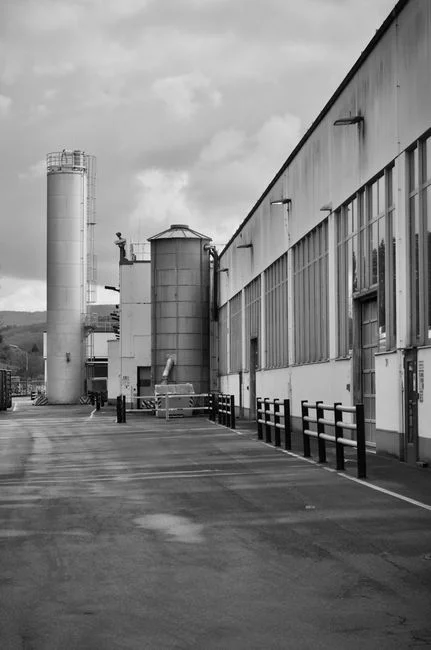
The most common DAF sizing failure on potato starch lines is sending a high-solids stream straight to the unit and asking it to compensate. Coarse screening with bar spacing of 3–6 mm must come first to remove peel fragments, tuber debris, and fibrous material that would blind skimmers, plug recycle nozzles, and erode the saturator internals. A GX series rotary mechanical bar screen is the typical choice because it handles the variable organic loading of a starch campaign without manual intervention. The target leaving the screens is TSS below 1,000 mg/L — well inside the DAF's design envelope. Equalization follows, sized at 8–24 hours of buffer volume to flatten the wet-season peaks and the washdown spikes; gentle aeration in the equalization tank prevents acidification from lactic fermentation and keeps sulfides down. Skipping either step forces the DAF into a wider operating envelope than the design parameters will support, and the symptom is breakthrough of floc into the clarified overflow during the September–October start-up when the biology in the equalization tank is not yet established.
Step 3: Coagulation and Flocculation Chemistry
DAF on potato starch water is a chemistry problem first and a hardware problem second. A three-stage chemical train is the standard: pH adjustment to 6.5–7.5 with lime or caustic soda, an optional ferric chloride dose of 30–80 mg/L for colloidal destabilization, then cationic polyacrylamide at 2–8 mg/L. Cationic charge is the right choice for starch–protein colloids because the granules carry a net negative surface charge; anionic flocculants underperform on this stream, while cationic polyacrylamide builds the charge patch and inter-particle bridge that produce dense, moderate-size flocs. Work on cationic starch derivatives for fine-particulate harvesting confirms that positively charged polysaccharides are effective at sweeping negatively charged particulates from suspension (Anthony, Utah State University, 2013, Cationic Starch Synthesis, Development, and Evaluation for Harvesting Microalgae for Wastewater Treatment), and the same mechanism applies to raw starch granules in process wastewater. Flocculation conditions matter as much as chemistry: 10–15 minutes at 20–40 rpm with a velocity gradient G ≈ 50–80 s⁻¹ produces flocs in the 100–500 µm band that 30–60 µm DAF microbubbles can attach to efficiently. Over-dosing polymer or over-flocculating generates very large, low-density flocs that sink rather than float and defeat the separation. A dedicated automatic chemical dosing system tied to a flow-proportional signal holds the dose inside the working window despite the wet-season hydraulic swings.
Step 4: DAF Sizing — The Core Calculations
The sizing math for a starch–protein DAF collapses to four equations and a parameter table. Surface loading rate (SLR) sits between 5 and 10 m³/m²·h, with the lower end of the band reserved for high-TSS wet-season flows where mass loading, not hydraulic loading, is the constraint. Tank area follows from A = Q / SLR, where Q is the design flow plus the pressurized recycle. Hydraulic residence time is the cross-check: HRT = V / Q should land between 15 and 25 minutes, which sets effective depth at 2.5–3.0 m for most designs. The pressurized recycle is 10–25% of the treated effluent stream, saturated at 5–6 bar, and produces 30–60 µm micro-bubbles — the size window where attachment kinetics and rise velocity are both favorable, as confirmed by pilot work on algae-laden water (Briley & Knappe, in CRC Press, 2024, Algae Laden Water Treatment by Dissolved Air Flotation). The air-to-solids ratio should land at 0.02–0.05 kg air per kg TSS removed.
| Parameter | Symbol | Design value | Unit / note |
|---|---|---|---|
| Surface loading rate | SLR | 5–10 | m³/m²·h; use 5–7 in wet season |
| Hydraulic residence time | HRT | 15–25 | min, in flotation zone |
| Effective tank depth | H | 2.5–3.0 | m |
| Pressurized recycle | R | 10–25 | % of treated effluent |
| Saturation pressure | P_sat | 5–6 | bar(g) |
| Microbubble size | d_b | 30–60 | µm |
| Air-to-solids ratio | A/S | 0.02–0.05 | kg air / kg TSS removed |
| Floc size target | d_f | 100–500 | µm |
| Flocculation G | G | 50–80 | s⁻¹ |
| Flocculation time | t_floc | 10–15 | min |
Worked example for a 50 m³/h design flow. Take Q = 50 m³/h, choose SLR = 8 m/h for a mid-season load, and set recycle at 20%. Q_total = 50 × 1.20 = 60 m³/h. Required flotation area A = 60 / 8 = 7.5 m² — round up to a standard 8 m² footprint. At effective depth 2.7 m, flotation volume is 21.6 m³, giving HRT = 21.6 / 60 = 0.36 h = 21.6 min, which lands inside the 15–25 min target. A standard dissolved air flotation system of 8 m² × 2.7 m handles this duty with margin for the wet-season SLR de-rating to 5 m/h if TSS exceeds 4,000 mg/L.
Step 5: Sludge Handling and Skimmer Design
Starch–protein float is sticky, fibrous, and prone to matting on the skimmer blade, so the float removal train must be specified with the same care as the flotation cell itself. A full-width skimmer with a replaceable scraper blade and an integrated spray wash bar prevents carry-back into the clarified water — without the spray, the float re-entrains and the effluent TSS climbs by 200–400 mg/L within an hour of operation. Float dry solids from a well-run starch DAF typically land at 3–6% w/w, and the float pump should be sized for 3–5% of the design flow on intermittent duty. For dewatering, route the float to a plate and frame filter press to reach 18–25% DS, or use a high-efficiency sedimentation tank as a thickener when the downstream destination is a biogas digester. The high carbohydrate content of starch float makes it a strong feed for anaerobic digestion, with methane yield potential often higher than the mixed activated-sludge stream from the biological stage — worth flagging in any energy-recovery review.
Step 6: Performance Targets and Compliance Benchmarks
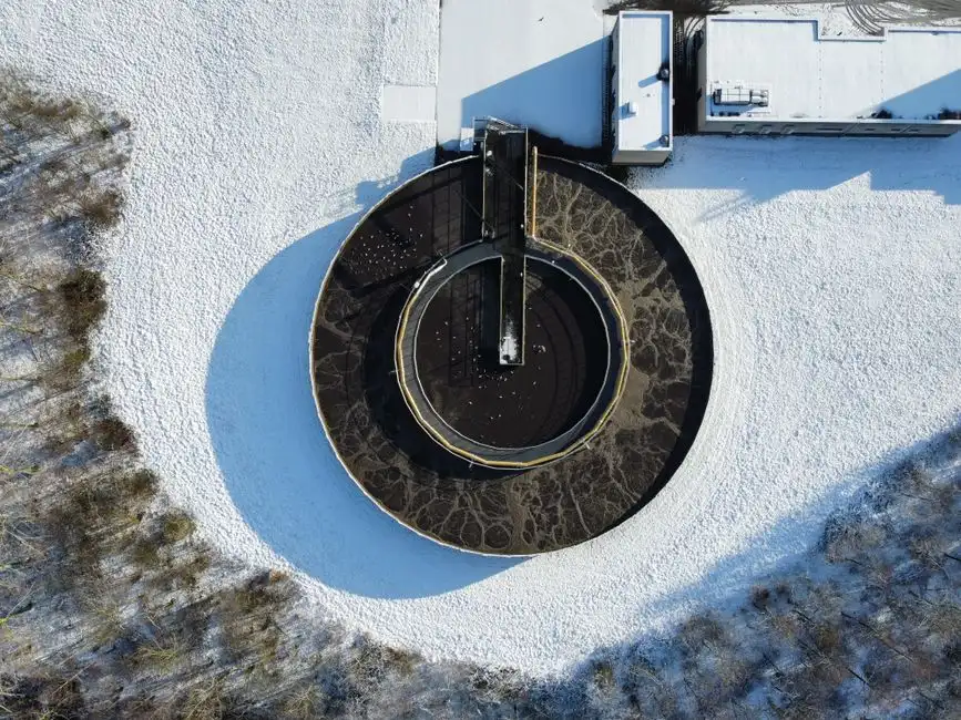
A properly coagulated potato starch DAF should deliver 80–90% TSS removal, 90–95% FOG removal, and 30–45% COD reduction. The COD that passes through is mostly soluble carbohydrate and protein, which the downstream biological stage (typically an anaerobic MBBR or MBR) is sized to handle. Effluent TSS leaving the DAF should sit between 100 and 250 mg/L — low enough to keep the biomass healthy, high enough to avoid re-suspension issues in equalization upstream of the biology. Removal efficiency is dominated by the flocculation step, not by the DAF hardware itself; the pilot work on floc size and density in DAF (Edzwald, 2024) shows that meeting the 80–90% TSS band requires holding floc size and density in the target window, which means online TSS and flow meters are not optional instrumentation. They are the feedback loop that lets the dose controller hold the chemistry in its working window during the September–October start-up and the February end-of-campaign ramp-down.
Frequently Asked Questions
What surface loading rate should I use for potato starch DAF?
Use 5–10 m³/m²·h, with the lower end (5–7) for high-TSS wet-season flows and the upper end (8–10) for low-TSS shoulder-season operation. Do not exceed 10 m/h on a starch–protein stream — bubble contact time falls off and floc breakthrough starts to appear in the clarified overflow above that rate.
Do I need a coagulant for potato starch water in DAF?
Yes. Cationic polyacrylamide at 2–8 mg/L, dosed after pH adjustment to 6.5–7.5, is the standard regime. Anionic flocculants underperform on negatively charged starch granules, and skipping the coagulant step drops TSS removal from 80–90% to 40–55% on a typical campaign stream.
What recycle ratio and saturation pressure do you recommend?
Pressurize 10–25% of treated effluent at 5–6 bar(g) to generate 30–60 µm micro-bubbles. Use the upper end of the recycle band (20–25%) at the start of the campaign when temperatures are warm and Henry's constant is high; the lower end (10–15%) is sufficient in colder shoulder-season operation.
Can one DAF cover both starch washwater and oily blanching water?
Yes, if both streams are equalized to a common pH and the same cationic polyacrylamide dose window works in jar tests. The combined stream typically carries 1,500–4,500 mg/L TSS and 200–800 mg/L FOG, both inside the design envelope of a single unit. If the jar test shows a wider dose split, run parallel trains — the chemistry mismatch will cost more in polymer and breakthrough than the second unit.
How do I handle the sticky float layer?
Specify a full-width skimmer with a spray wash bar to prevent carry-back, and route the float at 3–6% DS to a plate and frame filter press for dewatering to 18–25% DS. If the site has an anaerobic digester, the float is a strong co-feed due to its high carbohydrate content and will typically out-perform the waste-activated sludge on methane yield per kg VS.