What Makes Rack Wash Water a Hard MBR Feed
Rack wash water is the combined rinsate from paint racks, pretreatment hooks, and masking stations in automotive, aerospace, and metal-finishing lines. Flows run 5–500 m³/day and arrive in batch dumps tied to shift cycles, which drives COD swings of 2–5× from one batch to the next. A conventional activated sludge (CAS) plant is built for steady organic loading; rack wash water is the opposite — intermittent slugs of overspray paint (acrylic, epoxy, polyurethane), phosphate- or zirconium-based pretreatment chemistries, lubricant carryover, glycol from anti-spatter compounds, and fine suspended solids from rack abrasion all arrive in pulses rather than at a steady state.
Three failure modes follow. First, shock loadings knock out biomass; a CAS clarifier has no buffer volume to absorb a 5× COD swing without losing settleability. Second, free oil and glycol sheens coat clarifier surfaces, crushing floc formation and lifting sludge blankets. Third, unbound paint particles escape the clarifier effluent entirely, because their specific gravity is too close to water for gravity settling to remove them. The 2024 Springer review on MBR for high-strength industrial wastewater confirms this: the membrane physically decouples solids retention time (SRT) from hydraulic retention time (HRT), which is precisely what intermittent industrial feeds require, but fouling control becomes the binding constraint rather than biology (Springer, 2024).
The contamination profile that defeats CAS is the same profile that defeats an undersized MBR. Any specification has to start with the upstream chemistry — oil load, COD peak, TDS, and the ratio of slowly-biodegradable paint polymer to readily-soluble glycol — because those four numbers decide whether the MBR runs at design flux or collapses in three months.
Submerged vs Sidestream MBR: Which Configuration Fits Rack Wash Duty
A submerged PVDF flat-sheet MBR is the 2026 standard for rack wash water. Submerged modules sit directly in the aeration tank with 0.1 µm PVDF membranes, and coarse-bubble diffusers below each cassette scour the surface continuously while permeate is drawn by vacuum or gravity. A sidestream (external cross-flow) MBR instead circulates mixed liquor at 2–4 m/s through tubular or multichannel elements in a separate loop, relying on that high shear to keep the membrane surface clean.
The energy delta is not subtle. Submerged designs on rack wash duty consume 0.3–0.6 kWh/m³ for membrane scouring on top of process aeration; sidestream cross-flow pumping routinely adds 4–8 kWh/m³, which is the 10–20× penalty cited in the HydropureWater DF-series field data. That single line item is what disqualifies sidestream for most rack wash plants, regardless of any fouling-resistance argument.
Submerged wins on three other counts that matter here. (1) The larger aeration-tank volume absorbs intermittent COD and oil slugs that would otherwise slam a tight cross-flow loop. (2) Lower local shear at the membrane face means oil-tolerant operation is feasible — high cross-flow shear emulsifies free oil into the mixed liquor, which then blinds the membrane faster than it can be cleaned. (3) Footprint is roughly 40–60% smaller for the same throughput, because sidestream systems need a separate recirculation loop and often a second-stage housing. Sidestream remains defensible only when influent TSS exceeds 10,000 mg/L or feed temperature is above 40 °C, neither of which is typical of rack wash water. Where reuse is the goal, the 2024 Springer chapter on hybrid MBR-NF pilots confirms that nanofiltration or RO polish sits downstream of the MBR, not inside it.
| Parameter | Submerged PVDF Flat-Sheet | Sidestream Cross-Flow Tubular |
|---|---|---|
| Sustainable flux (LMH) on rack wash | 12–18 | 30–50 |
| Energy (kWh/m³ permeate) | 0.4–0.8 | 4–8 |
| MLSS tolerance (g/L) | 8–12 | 15–30 |
| Oil & grease tolerance (feed, mg/L) | 50–150 (post-DAF) | <30 |
| Footprint (relative) | 1.0× | 1.5–1.8× |
| Typical membrane area per 100 m³/day | 250–350 m² | 90–140 m² |
| Cleaning frequency (CIP) | Monthly | Weekly |
For project specification, the typical plant packages an integrated submerged MBR system around a PVDF flat-sheet MBR module cassette sized to the duty cycle above.
Pretreatment Train: Protecting the Membrane from Oil and Paint
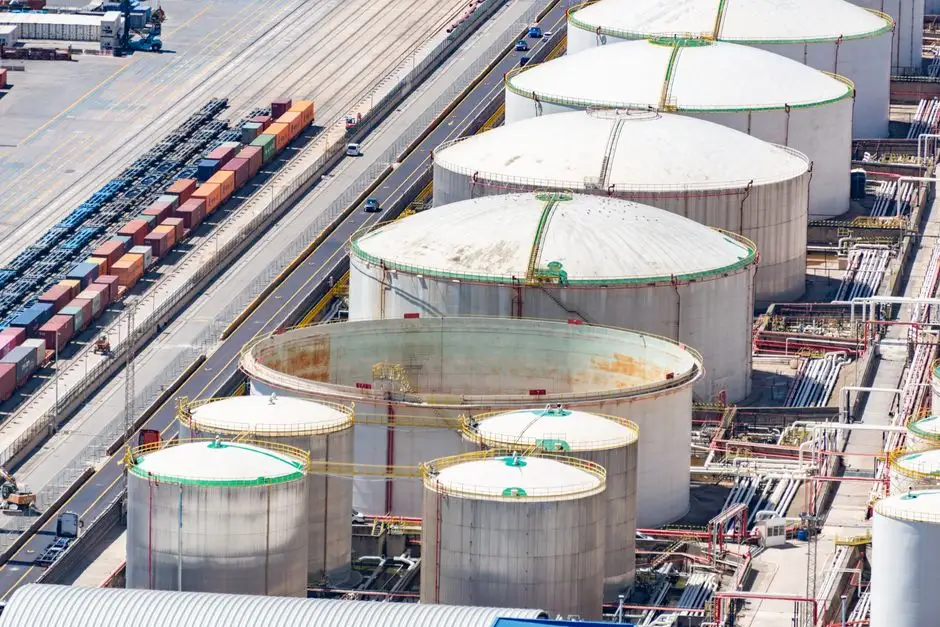
The MBR tank is only one stage of six. Pretreatment does the work that keeps the membrane alive, and undersizing it is the single most common cause of MBR failure on paint-bearing streams. A defensible 2026 train reads in this order.
- Coarse screening. A rotary bar screen headworks with 2–5 mm aperture removes masking tape debris, cardboard, hook fragments, and grit before they reach the DAF. Without this step, rag and string wrap around the DAF skimmer and starve the unit of surface area.
- Dissolved air flotation (DAF). A DAF oil and paint removal unit sized to peak shift flow (4–300 m³/h depending on plant size) lifts free oil, glycol, and non-adhered paint on micro-bubbles. Target effluent oil & grease below 30–50 mg/L — anything higher reaches the membrane as emulsified load and shows up as irreversible fouling within 60 days.
- Equalization. An EQ tank with mechanical mixing and pH probe smooths batch dumps from each rack station, targets 6.5–8.5 pH, holds temperature below 40 °C, and gives operators the buffer to ride out a slug.
- Nutrient dosing. PLC-controlled chemical dosing skids add urea and phosphoric acid when COD:N:P exceeds 100:5:1, which is common in polymer-rich paint wash. Skipping this step gives nitrification-limited biomass and foaming.
- Submerged MBR. The aeration tank with flat-sheet cassettes; SRT 30–60 days, HRT 6–12 hours.
- Optional RO polish. Required only when the reuse spec demands conductivity below 50 µS/cm, or when direct discharge requires TDS stripping beyond what the MBR can deliver.
Operating Parameters: Flux, MLSS, and Aeration Setpoints
The setpoint envelope below is what a commissioning engineer should be programming into the PLC on day one. These are starting values, not absolutes — every site will tune by 10–20% based on the actual influent fingerprint.
| Parameter | Submerged PVDF Flat-Sheet (Rack Wash) | Notes |
|---|---|---|
| Sustainable flux | 12–18 LMH | Reduce to 10 LMH if feed oil >50 mg/L post-DAF |
| MLSS | 8–12 g/L | Above 15 g/L raises viscosity and aeration cost sharply |
| Membrane aeration | 0.3–0.6 m³ air / m³ permeate | Continuous, on dedicated blowers |
| Process aeration | ~0.5 kg O₂ / kg COD removed | Sized to peak COD, not average |
| SRT | 30–60 days | Long SRT needed to degrade slow-biodegradable paint polymers |
| HRT | 6–12 hours | Longer HRT gives better equalization of batch dumps |
| CIP — weekly | Relaxation + backwash | Forward flush with permeate |
| CIP — monthly | NaOCl 500 mg/L + citric acid 1,000 mg/L | Frequency doubles if DAF is undersized |
The single most important detail: cleaning frequency is the leading indicator. If the operator is doing chemical CIP every two weeks instead of monthly, the problem is upstream of the membrane, not in it. Check DAF removal efficiency and oil carryover before assuming the membrane is the failure point.
Effluent Quality: Reuse vs Discharge Targets in 2026

A well-tuned submerged MBR on rack wash water produces TSS below 1 mg/L, turbidity below 0.5 NTU, COD 30–60 mg/L, BOD₅ below 5 mg/L, and oil & grease below 2 mg/L. That envelope is sufficient for most non-critical automotive and aerospace rinse loops (final-stage deionized rinse, pre-paint rinse, and parts washer make-up almost always need an RO polish stage to hit 50 µS/cm conductivity).
For direct discharge in the US, MBR permeate typically meets EPA categorical limits for metal finishing under 40 CFR 433 for TSS, oil & grease, and most metals, with confirmation sampling on the first 30 days of operation. In China, GB 8978-1996 Tier 1 covers the bulk parameters, and GB 30485-2013 (pharmaceuticals/chemicals industry effluent) adds heavy-metal monitoring on top of the standard COD/BOD/suspended solids envelope. If feed TDS is above 2,000 mg/L, MBR alone will not strip salts — RO or nanofiltration has to follow, and that changes both the CAPEX line and the concentrate disposal plan. A related process train for cleanroom applications is detailed in our guide to MBR configuration for cleanroom CIP wastewater.
2026 CAPEX and OPEX Envelope
Turnkey submerged MBR packages (including DAF, rotary screen, equalization tank, MBR cassette, blowers, and PLC controls) for a 100 m³/day rack wash plant sit at roughly USD 220K–380K CAPEX; for 500 m³/day, the range moves to USD 800K–1.4M. Sidestream configurations add 8–15% to CAPEX in pumps and external pipework, but that is the smaller line item — the OPEX penalty is what kills the sidestream case. Cross-flow pumping drives energy OPEX to 2–3× that of a comparable submerged system on the same feed.
OPEX drivers, in rank order: aeration energy (dominant), membrane replacement on a 5–7 year cycle (PVDF flat-sheet, ~USD 25–40 per m² installed, source: HydropureWater field data 2026), chemical cleaning agents (NaOCl and citric acid, ~3–5% of total OPEX), and waste activated sludge hauling from the WAS bleed. Comparable envelope figures for a different high-strength industrial feed appear in our guide to MBR configuration for print paste wash.
Selection Decision Framework
Use this four-branch decision tree to lock the configuration before talking to procurement.
- Reuse for non-critical rinsing (parts wash, gross deionized rinse, cooling tower make-up): submerged PVDF flat-sheet MBR, no RO, feed TDS below 2,000 mg/L.
- Reuse for critical pre-paint or DI feed: submerged MBR plus RO polish, target permeate conductivity below 50 µS/cm.
- Direct discharge under EPA 40 CFR 433 or equivalent local limits: submerged MBR alone is typically compliant on TSS, oil & grease, and metals; confirm local metals and TDS caps with a 30-day confirmation trial.
- Feed oil & grease above 150 mg/L or TSS above 3,000 mg/L: revisit DAF sizing and consider a two-stage DAF before sizing the MBR; no membrane chemistry will compensate for a fouling load that upstream should be removing.
Frequently Asked Questions
What MBR configuration treats rack wash water for reuse or discharge?
A submerged PVDF flat-sheet MBR is the standard 2026 configuration for rack wash water. It handles high COD swings, lubricant carryover, and intermittent paint slugs at 0.3–0.6 kWh/m³ energy, versus 4–8 kWh/m³ for a sidestream cross-flow design. Permeate typically meets TSS below 1 mg/L and COD 30–60 mg/L, suitable for non-critical reuse or EPA 40 CFR 433 / GB 8978-1996 discharge after optional RO polishing.
Why does a conventional activated sludge plant fail on rack wash water?
Rack wash arrives in batch dumps with COD swings of 2–5×, free oil, glycol, and unbound paint particles. CAS has no buffer volume to absorb the slug, oil sheens coat clarifier surfaces and collapse floc, and paint particles escape the clarifier because their specific gravity is too close to water. The 2024 Springer review on MBR for high-strength industrial wastewater confirms that decoupling SRT from HRT is what makes MBR viable on this feed.
When is a sidestream MBR still the right choice for rack wash water?
Only when influent TSS exceeds 10,000 mg/L or feed temperature runs above 40 °C — both outside the normal rack wash envelope. For typical 5–500 m³/day automotive, aerospace, or metal-finishing streams, the 10–20× energy penalty of cross-flow pumping rules out sidestream unless the duty case forces it.
How often should the MBR be chemically cleaned on rack wash duty?
Plan for weekly relaxation backwash and monthly chemical CIP using NaOCl at 500 mg/L plus citric acid at 1,000 mg/L. Cleaning frequency above that baseline is a diagnostic signal — the DAF is almost always undersized, or the EQ tank is not buffering slug loads, not the membrane itself.