
Why the LGES 2026 Expansion Changes the ETP Sizing Equation
LG Energy Solution has publicly committed to 110 GWh of cumulative U.S. cell capacity by 2026, anchored by a 35 GWh Ohio joint venture with Honda and a parallel 5 GWh Michigan standalone line (per lgenergymi.com). On the Korean side, the Ochang complex is absorbing KRW 4 trillion (≈USD 3.1 billion) through 2026 to scale cylindrical cell output, adding 1,800 jobs (per EnergyTrend, 2023-01). That is the scale a process engineer has to translate into cubic meters per day before a single pipe is routed.
The rule of thumb for NMC cathode lines is 60–120 L of process wastewater per kWh of cell produced, of which roughly 70% originates at electrode coating, 20% from formation cycling and electrolyte mixing, and 10% from electrode drying condensation. Applied to the 35–110 GWh envelope, that gives a design window of 5,000–18,000 m³/day for the main treatment train, with a separate 1,000–3,000 m³/day low-COD condensate sidestream from dry-room humidification. Cell assembly, stacking, and module packaging are minor water consumers by comparison and rarely drive ETP capacity.
The sizing pivot matters because the top three search results for this query are a Microsoft API reference, an LGES Michigan corporate page, and a 2023 investment news item — none of them contain a single m³/day number. The capacity figure above is the line item a reviewer will want to see first in any feasibility memo.
Influent Characterization: What Is Actually in LGES-Style Battery Wastewater
An NMC cathode line generates a wastewater matrix that conventional municipal design assumptions cannot absorb. The compounds below are the ones an EPC engineer has to defend in a process design basis before selecting equipment.
| Parameter | Typical range (raw) | Source |
|---|---|---|
| COD | 2,000–8,000 mg/L | NMP solvent + PVDF binder carryover |
| BOD₅/COD ratio | 0.25–0.40 | Low — biologically hard |
| Fluoride (F⁻) | 50–500 mg/L | LiPF₆ electrolyte hydrolysis |
| Suspended solids | 500–3,000 mg/L | Graphite/cathode powder, CMC/SBR flocks |
| Co + Ni + Mn (total) | 5–50 mg/L | Cathode coating wash water |
| pH | 8.5–11.0 | Alkaline cleaning steps |
| Temperature | 25–45 °C | Coating dryer condensate |
| NH₃-N | 100–400 mg/L | Formation cycling electrolyte breakdown |
The BOD₅/COD ratio of 0.25–0.40 is the parameter that kills conventional activated sludge designs. Biomass cannot feed on NMP or PVDF to any meaningful degree, so the carbon load has to be oxidized physically or chemically before biology sees it. Fluoride above 30 mg/L is inhibitory to nitrifiers, so any biological stage must be downstream of a precipitation step — which is why the train in the next section sequences fluoride removal before the MBR. For nitrification kinetics on this specific NH₃-N band, the ammonia-nitrogen wastewater treatment engineering guide covers the recommended SRT and DO setpoints.
Treatment Train Engineering: How a 2026 ETP for an LGES-Scale Plant Is Built
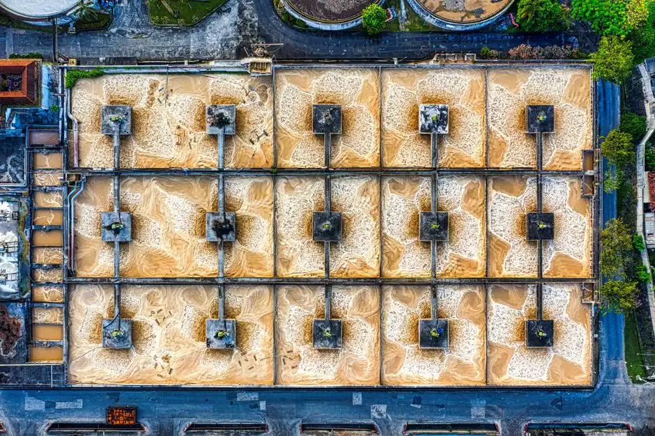
The train below sequences six unit operations so that each stage hands a stream the next stage can actually handle. Skipping or reordering any of them creates either a fouled membrane or a non-compliant effluent.
- Stage 1 — NMP recovery distillation. Vacuum distillation at 80–120 mbar recovers 90–95% of NMP from the coating wastewater for return to the electrode plant. Distillate polishing through activated carbon strips residual organics to below 50 mg/L COD before the stripped water rejoins the main ETP feed.
- Stage 2 — Equalization and pH correction. An 8–24 hour HRT buffer basin homogenizes batch dumps from coating campaigns and trims pH to 7.0–8.0 using CO₂ or H₂SO₄ dosing via a PLC-controlled chemical dosing system for CaCl₂, PAC, and pH correction.
- Stage 3 — Coagulation and DAF. PAC at 200–400 mg/L plus anionic flocculant at 1–3 mg/L drives 85–95% removal of suspended cathode powder and PVDF binder flocks. A dissolved air flotation system for cathode powder and PVDF binder removal with 50–80 µm micro-bubbles is the standard selection at this flow class.
- Stage 4 — Fluoride precipitation. CaCl₂ dosing at 1.5–2.0× stoichiometric (stoichiometric demand ≈ 2.27 mg CaCl₂ per mg F⁻) drops fluoride below 20 mg/L; a downstream F⁻-selective media polish (activated alumina or LAN) brings residual F⁻ to under 10 mg/L to protect the biology.
- Stage 5 — MBR. A submerged PVDF MBR system for COD and ammonia polishing with 0.1 µm membranes operates at MLSS 8,000–12,000 mg/L, SRT 25–35 days, and DO 2–4 mg/L. The high-TDS, low-F/M regime favors MBR over conventional activated sludge because the membranes retain the slow-growing nitrifiers that a clarifier would wash out. Effluent targets: COD <150 mg/L, NH₃-N <10 mg/L.
- Stage 6 — RO and ZLD on the reject. An industrial RO system for electrode-coating rinse reuse runs at 95% recovery, producing permeate at <50 µS/cm suitable for rinse-water makeup. The 15–20% reject stream is routed to a mechanical vapor recompression (MVR) or multi-effect evaporator plus crystallizer for zero liquid discharge, since LGES's Ochang site already operates under a tight water-reuse mandate.
Sizing the ETP: From GWh Output to m³/day Capacity
The fastest defensible sizing path multiplies the per-cell wash-water demand by annual cell output and divides by operating hours. For a 60 GWh/year NMC line coating 0.4 m² of electrode per cell across 12 coating passes at 8 L/m² wash water, single-shift production generates roughly 9,600 m³/day. Add 30% for formation cycling and electrolyte rinse, and the design flow lands near 12,500 m³/day.
| Plant capacity (GWh/year) | Process wastewater (m³/day) | With 20% standby train (m³/day) | Notes |
|---|---|---|---|
| 35 (Ohio JV) | 5,000–6,500 | 6,000–7,800 | Single NMC line, one shift baseline |
| 60 (Ochang expansion) | 9,000–12,500 | 10,800–15,000 | Two coating lines, mixed shift loading |
| 110 (U.S. target) | 14,000–18,000 | 16,800–21,600 | Three to four coating lines, 1.3 peaking factor |
Apply a 1.3 peaking factor for shift-based loading and provision a 20% standby train for the largest unit out for maintenance. A separate sidestream of 1,000–3,000 m³/day of low-COD condensate from dry-room humidifiers can be blended into the RO feed or reused as boiler makeup after carbon filtration.
2026 Compliance Framework: EPA, EU IED, K-ME, and China GB 30484
An LGES battery plant is unusual because it can be sited under four different discharge regimes depending on the geography of the project. The defensible approach is to design against the strictest of the four so the same skid can be redeployed without rework.
| Regime | Standard | COD (mg/L) | F⁻ (mg/L) | Ni (mg/L) | Zn (mg/L) |
|---|---|---|---|---|---|
| U.S. — Ohio | 40 CFR Part 468 (Battery Mfg) | 247 (daily max) | — | 1.0 | 1.0 |
| EU | IED 2010/75/EU BAT-AEL (indirect discharge) | <100 | — | — | — |
| Korea | Ministry of Environment industrial effluent | ≤120 | ≤3 | — | — |
| China | GB 30484 (battery industry) | ≤150 | — | 0.5 (total) | — |
Korea's 3 mg/L fluoride ceiling and the EU's 100 mg/L COD ceiling are the binding constraints in most cross-border proposals. A single design basis that targets COD ≤80 mg/L, F⁻ ≤2 mg/L, and total Ni ≤0.3 mg/L satisfies all four regimes simultaneously. For a parallel cross-walk against semiconductor-style discharge limits — a frequent request when an LGES line is co-located with a chip fab — see the 2025 third-generation semiconductor wastewater discharge standards and ZLD compliance blueprint.
CAPEX, OPEX, and Recovery Economics for the 2026 Build
Budget reviewers will want a single table to anchor the capex conversation, broken out by the major cost blocks an EPC contractor prices on a turnkey basis.
| Item | Benchmark value (2026) | Basis |
|---|---|---|
| CAPEX — main ETP train | USD 280–520 per m³/day installed | 5,000–18,000 m³/day class, mid-size EPC |
| OPEX — treatment cost | USD 0.35–0.75 per m³ treated | NMP makeup, CaCl₂, RO membrane replacement |
| NMP recovery payback | 18–30 months | 60–80% solvent recovery at 2026 NMP spot pricing |
| ZLD brine handling add-on | USD 1.2–1.8 M per 1,000 m³/day brine | MEE + crystallizer for the 15–20% RO reject |
For a 12,500 m³/day NMC line, the main train alone lands between USD 3.5M and USD 6.5M, with another USD 1.5M–2.3M for the ZLD evaporator train handling the roughly 2,000 m³/day of RO reject. The NMP recovery column is the single fastest-paying piece of equipment: at 80% recovery on a 60 GWh line consuming 1,200–1,800 t/year of virgin NMP, solvent cost avoidance covers the column within two operating years.
Frequently Asked Questions
What is the typical CAPEX for a battery gigafactory ETP in 2026? A 5,000–18,000 m³/day lithium-ion battery wastewater treatment plant installs for USD 280–520 per m³/day in 2026, with the ZLD brine add-on priced separately at USD 1.2–1.8 million per 1,000 m³/day. A 12,500 m³/day NMC line therefore budgets USD 3.5–6.5 million for the main train (per HydropureWater field data, 2026).
How much NMP can be recovered from cathode coating wastewater? Vacuum distillation at 80–120 mbar recovers 90–95% of NMP from the coating wastewater, with 60–80% of the recovered solvent meeting reuse purity. The recovered NMP offsets virgin solvent purchases and pays back the distillation column in 18–30 months at current NMP spot pricing.
Which compliance regime applies to an LGES Ohio plant? Ohio sites discharge under U.S. EPA 40 CFR Part 468 with daily maximum limits of COD ≤247 mg/L, Ni ≤1.0 mg/L, and Zn ≤1.0 mg/L. The recommended design basis targets COD ≤80 mg/L and total Ni ≤0.3 mg/L so the same skid can be redeployed to an EU or Korea site without rework.
What is the most challenging wastewater stream to treat in a gigafactory? The fluoride-bearing stream from LiPF₆ electrolyte hydrolysis is the hardest because fluoride above 30 mg/L inhibits nitrification, and the Korea 3 mg/L F⁻ ceiling requires a CaCl₂ precipitation stage followed by selective media polish before any biological unit.
How should battery manufacturing sludge be handled downstream? Cathode-laden DAF sludge and MBR waste are typically dewatered via a chamber filter press to 35–40% dry solids, then sent to a licensed hazardous-waste facility for cobalt and nickel recovery. For a full process breakdown, see the battery manufacturing wastewater sludge treatment process guide, and for a hot-climate variant with high-TDS intake, the battery manufacturing wastewater treatment in Egypt engineering guide covers ambient-temperature adjustments to the same train.


