Why Tesla's Giga Texas Wastewater Process Matters for the EV Industry
Zero of the top three Google results for "How does Tesla treat wastewater at its Gigafactory Texas plant?" actually document the wastewater process. The highest-ranking page (AutoSpies, citing Electrek) reports Tesla filed 10 new permit applications to double a factory that already spans over 5 million square feet, but never identifies the treatment train. Pages 2 and 3 are unrelated technical content. Four-plus years of production data sit fragmented across TCEQ filings, Tesla Impact Reports, and the EPA ECHO database, with no consolidated engineering reference.
That gap matters because every new EV or battery gigafactory now faces the same regulatory and design pressure. EV manufacturing wastewater is uniquely complex: NMP solvent from cathode coating, graphite slurries from anode production, LiPF6 electrolyte salts, plus conventional metalworking rinse streams from body shop all converge on a single site. Reverse-engineering Tesla's process train from public sources gives engineers a defensible design baseline rather than a blank sheet.
This article reconstructs the probable Giga Texas process train from TCEQ TPDES permit structure, Tesla sustainability disclosures, and documented Giga Berlin/Nevada practice, then packages it as a replicable design framework with parameter tables and equipment specifications.
The Wastewater Streams Generated at a Tesla Gigafactory
Giga Texas segregates at least five distinct wastewater streams because mixing them would create treatment conflicts and inflates CAPEX. Each stream's chemistry dictates its pretreatment path before any biological or membrane step.
- Cathode production stream: NMP (N-methyl-2-pyrrolidone) solvent carrier, PVDF binder, carbon black conductive additive, and trace lithium, nickel, and cobalt. High-COD (typically 5,000–20,000 mg/L), solvent-bearing, and incompatible with direct biological treatment until NMP is stripped or recovered.
- Anode production stream: graphite slurry, CMC/SBR binder chemistry, and deionized rinse water. Moderate suspended solids (approximately 500–2,000 mg/L), low dissolved metals, but high TSS loads that require clarification before discharge or reuse.
- Vehicle assembly stream: phosphating rinse, e-coat paint overflow, and body shop wash water. Contains zinc and nickel from pretreatment, phosphate, oil and grease, and surfactants. Subject to categorical metal finishing effluent limits under 30 TAC Chapter 307.
- Cooling tower and boiler blowdown: high TDS (1,000–3,000 mg/L), silica, and scale inhibitor residues. Typically handled separately and blended for RO recovery or evaporation.
- Domestic sewage: from a workforce exceeding 10,000 employees. Handled via on-site package plant or municipal connection, and kept segregated from industrial streams to avoid hydraulic and biological loading shocks.
| Stream | Key Contaminants | Typical Concentration | Primary Treatment |
|---|---|---|---|
| Cathode coating | NMP, PVDF, Li/Ni/Co | COD 5,000–20,000 mg/L | Distillation recovery, then biological |
| Anode slurry | Graphite, CMC/SBR | TSS 500–2,000 mg/L | Clarification, filtration |
| Body shop/assembly | Zn, Ni, phosphate, FOG | FOG 50–200 mg/L; Ni 2–10 mg/L | DAF, metal precipitation |
| Cooling tower blowdown | TDS, silica, scale inhibitors | TDS 1,000–3,000 mg/L | RO, side-stream softening |
| Domestic sewage | BOD, pathogens | BOD 200–400 mg/L | Package activated sludge or municipal |
Tesla Giga Texas Wastewater Treatment Process: Unit Operations
The probable Giga Texas treatment train runs in seven stages. Each stage addresses a specific stream characteristic identified in the table above; together they convert mixed industrial influent into reuse-quality water plus a concentrated brine reject.
Stage 1 — Equalization and neutralization. Surge basins balance pH swings from 2 to 11 generated when cathode wash water and anode rinse water converge. A PLC-controlled pH adjustment and coagulant dosing skid brings the mixed stream to 6.5–7.5 before downstream processes. Equalization typically smooths 6–12 hours of hydraulic and load variation.
Stage 2 — Dissolved air flotation (DAF). A DAF system for oil and grease removal strips free oil, grease, and floated solids from the combined body shop and cathode coating streams. Expected FOG removal: 80–95% at hydraulic capacities of 4–300 m³/h depending on skid size. DAF effluent feeds the next stage with TSS typically below 100 mg/L.
Stage 3 — Coagulation/flocculation and lamella clarification. Dosed coagulants (typically ferric chloride or polyaluminum chloride) precipitate dissolved nickel, cobalt, and lithium as hydroxides at pH 9–10. Lamella clarifiers with surface loading rates of 20–40 m/h separate the metal-rich sludge, which is sent to a filter press for dewatering.
Stage 4 — NMP recovery (closed loop). A vacuum distillation column recovers NMP from the cathode wastewater concentrate for reuse in coating operations. This is solvent management, not treatment: recovered NMP returns to the process, and the aqueous bottoms advance to biological treatment with substantially reduced COD loading.
Stage 5 — Biological treatment (MBR). A submerged MBR membrane bioreactor with PVDF hollow-fiber modules reduces COD and BOD while delivering effluent turbidity below 1 NTU. The membrane barrier eliminates suspended solids in the clarifier effluent and supports mixed liquor suspended solids (MLSS) of 8,000–12,000 mg/L. Reactor volume is sized to peak flows of approximately 5,000 m³/day.
Stage 6 — Reverse osmosis polishing. A two-pass industrial RO system for water reuse polishes MBR permeate to conductivity below 50 µS/cm, suitable for cooling tower makeup and process rinse water. System recovery: 70–85%; brine reject (15–30% of feed) is sent to on-site evaporation or to an industrial waste hauler for off-site disposal.
Stage 7 — Disinfection. Reuse or discharge water receives a final chlorine dioxide or UV step before returning to the cooling loop or outfall. The chlorine dioxide generator range covers capacities from 50 g/h to 20,000 g/h to match anything from a single skid to a full gigafactory.
Influent and Effluent Parameters: What Giga Texas Must Meet
Tesla's design must hold TCEQ-mandated effluent limits while pushing 60–80% of the treated water back into the plant. The numbers below combine permit structure, Tesla Impact Report 2023 disclosure ("approximately 1.4 million gallons reused daily" at Giga Texas), and typical EV/battery industry influent profiles.
| Parameter | Influent Range | Effluent Limit (TCEQ 30 TAC Ch. 307) | Reuse Target |
|---|---|---|---|
| Total flow | 8,000–15,000 m³/day | — | 60–80% recycled |
| COD | 1,500–3,000 mg/L | — (BOD5 limit applies) | — |
| BOD5 | 800–1,500 mg/L | ≤30 mg/L | — |
| TSS | 300–800 mg/L | ≤30 mg/L | — |
| FOG | 50–200 mg/L | ≤15 mg/L | — |
| Total nickel | 2–10 mg/L | ≤1.0 mg/L | — |
| Total cobalt | 1–5 mg/L | ≤1.0 mg/L | — |
| pH | 2–11 | 6.0–9.0 | — |
| TDS (reuse loop) | — | — | <500 mg/L |
Brine reject from the RO stage concentrates the salts and scale inhibitors removed during treatment. That reject stream is the single largest barrier to higher reuse rates and is typically the limiting factor for any site pursuing the 95%+ reuse targets that Giga Shanghai reportedly achieves.
Regulatory Framework: TCEQ, EPA, and Travis County Oversight
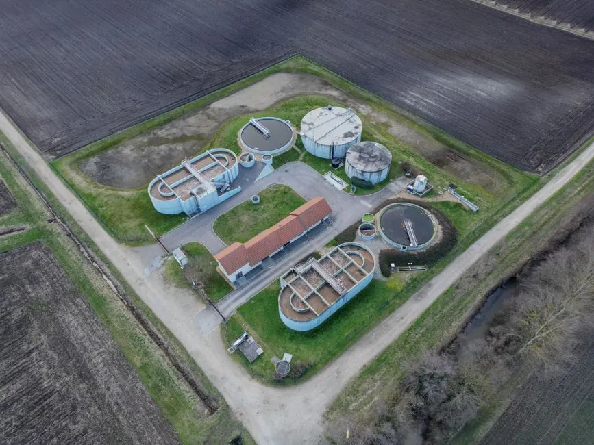
Tesla Giga Texas operates under multi-sector TPDES (Texas Pollutant Discharge Elimination System) coverage administered by the Texas Commission on Environmental Quality. The plant's actual permit is an individual permit because the combined flow exceeds the 50,000-gallon-per-day threshold for the multi-sector general permit TXR050000; smaller satellite operations on the same site may still be covered by the general permit. Discharge points fall under 30 TAC Chapter 307 (Texas Surface Water Quality Standards), with effluent limits tracking the metal finishing categorical standard (40 CFR 433) for the body shop stream and the battery manufacturing subcategory for the cathode and anode streams.
The EPA ECHO database maintains the plant's Discharge Monitoring Reports (DMRs) on a quarterly cadence. Cross-checking the 2024–2025 ECHO records for any DMR exceedances is a standard pre-acquisition due diligence step for ESG analysts benchmarking Tesla's water performance. Annual Toxic Release Inventory (TRI) reporting under EPCRA Section 313 is required for nickel, cobalt, and NMP because each exceeds the threshold quantity. Travis County additionally enforces stormwater requirements under TPDES for construction runoff from the ongoing site expansion, which is why the 10 new permit applications cited in the top-ranking search result all carry water-quality implications beyond building footprint.
Replicating the Giga Texas Approach for a New EV or Battery Plant
For a new EV or battery plant under 2,000 m³/day, the MBR + RO backbone scales down proportionally. The full Giga Texas treatment train (excluding NMP distillation) fits a CAPEX envelope of $1.5M–$6M depending on flow, effluent limits, and reuse target, which is documented in detail in our MBR vs MBBR cost comparison guide. Plants that outsource cathode production to a Tier 1 cell supplier can skip the NMP distillation column entirely, but still need DAF plus MBR for body shop and assembly streams, and RO for cooling tower makeup.
A practical equipment checklist for a 1,500 m³/day battery plant:
- Rotary bar screen (2 mm aperture) for gross solids removal
- Equalization tank (12-hour retention) with mixers and level control
- Automatic chemical dosing skid for pH, coagulant, and polymer
- DAF unit sized to peak hourly flow
- Lamella clarifier for metal hydroxide precipitation
- MBR tank with PVDF membrane modules
- Two-pass RO system with CIP skid
- Chlorine dioxide generator for disinfection
- Sludge dewatering filter press for metal-rich clarifier underflow
The MBR+RO train matches the design deployed at Giga Berlin and aligns with Giga Shanghai's higher-reuse configuration. Tesla's published 2030 target of zero liquid discharge at all gigafactories implies the next-generation train will add an evaporation or crystallizer stage to the RO reject, which is the same direction the broader battery manufacturing wastewater sludge treatment and metal finishing wastewater treatment process industries are moving as discharge limits tighten.
Frequently Asked Questions
What TCEQ permit governs Tesla Giga Texas wastewater discharge?
The plant operates under an individual TPDES permit administered by TCEQ, with effluent limits set under 30 TAC Chapter 307. Some satellite operations on the site are covered under multi-sector general permit TXR050000. Quarterly DMRs are publicly searchable in the EPA ECHO database.
How much water does Giga Texas recycle per day?
Tesla's 2023 Impact Report states the site reuses approximately 1.4 million gallons per day, which corresponds to the 60–80% reuse range typical of the MBR+RO configuration.
Does Tesla treat NMP solvent from cathode production?
NMP is recovered via vacuum distillation and returned to the coating process in a closed loop, not discharged. Only the aqueous distillation bottoms advance to biological treatment, which dramatically reduces the influent COD load on the MBR stage.
What effluent limits apply to heavy metals at Giga Texas?
Under the metal finishing categorical standard, total nickel must be below 1.0 mg/L and total cobalt below 1.0 mg/L in the discharge. The site's permit may set tighter limits depending on the receiving stream's assimilative capacity in the Colorado River basin.
Can the Giga Texas treatment process be scaled for a smaller battery plant?
Yes. The DAF, MBR, and RO stages scale linearly from 100 m³/day to over 15,000 m³/day. NMP distillation is only required for sites running in-house cathode coating; plants that buy cells from a Tier 1 supplier can omit that stage entirely.