Why Adhesive and Sealant Wastewater Is Unusually Hard to Treat
Adhesive and PSA tape lines typically generate 5–25 m³/h of wastewater with COD of 5,000–25,000 mg/L, BOD/COD ratios of 0.25–0.45, TSS of 2,000–8,000 mg/L, and emulsified acrylic or PVA polymer loadings of 500–3,000 mg/L, frequently carrying residual solvents (ethyl acetate, acetone, toluene) and plasticizers such as DOP and DINP. The dominant load comes from coater-cleaning cycles on tape lines, which per the ResearchGate adhesive-tape study release intermittent slugs of uncured polymer, release-agent, and surfactant that drive COD spikes above 30,000 mg/L and suspended solids above 10,000 mg/L within minutes. Three structural problems defeat generic municipal-style designs: colloidal stability from the surfactant-stabilized emulsion (zeta potential often −30 to −50 mV), biomass toxicity from solvent carry-over at concentrations above roughly 200 mg/L, and batch pH swings between 2 and 11 driven by acid-catalyzed resin washes alternating with alkaline cleaning steps. A standard activated-sludge plant sized for municipal sewage collapses on the first solvent slug; the design must treat the wastewater as a separate industrial stream.
2026 Discharge Targets and Regulatory Benchmarks
China's GB 8978-1996 second-class standard remains the most common project baseline in 2026: COD ≤150 mg/L, BOD ≤30 mg/L, SS ≤150 mg/L, pH 6–9, with total nitrogen and total phosphorus addressed by the local 2026 integrated discharge standard rather than the original 1996 document. Plants serving European customers must also meet EU Industrial Emissions Directive 2010/75/EU BAT-AEL ranges for the surface-treatment of metals and plastics sector, while U.S. sites typically discharge under EPA 40 CFR Part 433 metal-finishing limits, which set a daily maximum oil and grease of 52 mg/L and TSS of 60 mg/L — both stricter than the Chinese second-class standard for the same parameters. Several Chinese provinces tightened nutrient limits in 2026: Jiangsu and Zhejiang now enforce total nitrogen ≤40 mg/L and total phosphorus ≤2 mg/L for new discharge permits in sensitive watershed districts, and the Yangtze River Economic Belt enforces a COD ≤50 mg/L ceiling for new plants near source-water zones. Always re-confirm against the local 2026 integrated discharge standard before freezing a design.
| Region / Standard | COD (mg/L) | BOD (mg/L) | SS (mg/L) | TN (mg/L) | TP (mg/L) | Notes |
|---|---|---|---|---|---|---|
| China GB 8978-1996, 2nd class | ≤150 | ≤30 | ≤150 | — | — | Baseline; verify with 2026 local standard |
| Jiangsu / Zhejiang 2026 update | ≤150 | ≤30 | ≤100 | ≤40 | ≤2 | New permits in sensitive districts |
| EU IED 2010/75/EU BAT-AEL | ≤130 | — | ≤30 | ≤15 | ≤2 | Surface-treatment BAT |
| U.S. EPA 40 CFR 433 | — | — | ≤60 (daily max) | — | — | O&G ≤52 mg/L daily max |
Full Process Flow: Equalization to Permeate
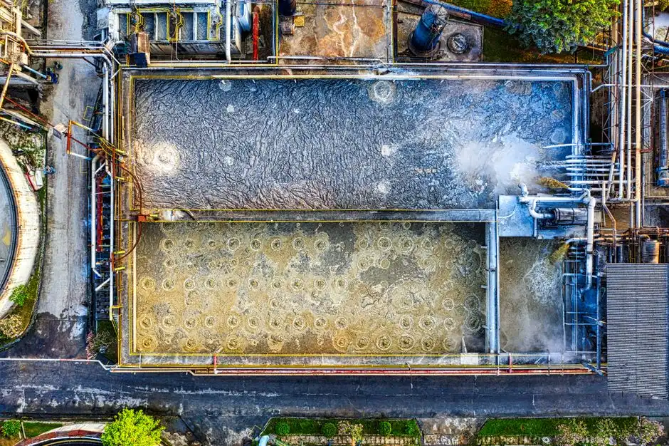
The canonical 2026 treatment train for a 10 m³/h acrylic PSA tape line runs in six stages, each with a defined operating envelope.
Step 1 — Equalization and neutralization. An 8–24 h HRT equalization basin damps flow variation to ≤10% and brings pH into the 6.5–8.0 range with NaOH or H₂SO₄ dosing from an automatic coagulant and pH dosing skid. Continuous pH and conductivity monitoring is non-negotiable; an online VOC sensor upstream of the equalization tank is the cheapest insurance against biomass kill downstream.
Step 2 — Coagulation or electrocoagulation. Per Lu et al. 2022, electrocoagulation with Al/Fe electrodes at 10–30 A/m² and 20–40 min contact time removes more than 85% of suspended solids and breaks the colloidal emulsion before biological treatment. Chemical coagulation with PAC (200–500 mg/L) plus anionic PAM (2–5 mg/L) is the conventional fallback for plants without rectifier capacity.
Step 3 — Dissolved Air Flotation (DAF). A DAF system for emulsified polymer removal operating at surface loading of 5–20 m/h skims the floated sludge and typically removes 70–90% of residual TSS and emulsified polymer. Micro-bubble saturation pressure of 4–6 bar with 30–40% recycle is standard for 2026 designs.
Step 4 — Anaerobic biofilm / UASB. Per the Industrial Waste Treatment Handbook, an RBC-style anaerobic biofilm reactor or UASB with return sludge handles 5,000–25,000 mg/L COD with 60–80% lower aeration energy than activated sludge; COD removal typically lands at 70–85% at 24–48 h HRT and 35–37 °C. For a deeper look at the trade-offs, see the DAF advantages and disadvantages engineering guide.
Step 5 — MBR polishing. A submerged submerged PVDF flat-sheet MBR module at 0.1–0.4 µm drives TSS below 1 mg/L and residual COD to 100–500 mg/L at flux of 10–20 L/m²·h. A complete MBR system for COD and TSS polishing packages the tank, aeration, and CIP in one skid for 2026 retrofits.
Step 6 — UF / RO polish. The U.S. EPA explicitly endorses ultrafiltration as a viable process for separating adhesives and sealants manufacturing wastewaters into a low-volume concentrate and a reusable permeate; RO is added when water reuse ≥70% is required. For related emulsified streams, the emulsified oil wastewater treatment guide gives a parallel mass balance.
Influent and Effluent Parameters at Each Stage
The single most-copied asset in this guide is the stage-by-stage mass balance. The table below maps each unit operation onto the influent/effluent envelope a process engineer can drop into a P&ID or a regulator submission, anchored to a 10 m³/h acrylic PSA tape line at 18,000 mg/L COD. Numbers reflect HydropureWater field data, 2026, cross-checked against Lu et al. 2022 and the Industrial Waste Treatment Handbook.
| Stage | Typical Influent | Typical Effluent | Key Removal | Operating Note |
|---|---|---|---|---|
| Raw wastewater | COD 18,000; TSS 5,000; pH 4–9 | — | — | Solvent spikes >200 mg/L trigger equalization alarm |
| Equalized | COD 17,000; TSS 4,500; pH 7.0 ±0.3 | COD 17,000; TSS 4,500 | Flow dampened to ±10% | 8–24 h HRT; online pH and conductivity |
| Post-electrocoagulation | COD 14,500; TSS 700; oil 80 | COD 14,500; TSS 700 | TSS −86%; oil −92% | 10–30 A/m², Al/Fe electrodes, 20–40 min |
| Post-DAF | COD 13,800; TSS 50; oil 25 | COD 13,800; TSS 50 | TSS −93%; oil −69% | Surface loading 5–20 m/h; 30–40% recycle |
| Post-anaerobic biofilm | COD 1,800; BOD 350; TSS 200 | COD 1,800; BOD 350 | COD −87%; BOD −88% | 24–48 h HRT, 35–37 °C, biogas 0.30–0.40 m³/kg COD |
| Post-MBR | COD 350; BOD 25; TSS <1 | COD 350; BOD 25; TSS <1 | COD −81%; TSS −99% | Flux 10–20 L/m²·h; CIP every 2–4 weeks |
| Post-UF permeate | COD 130; TSS <1; turbidity <0.5 NTU | COD 130; TSS <1 | COD −63%; turbidity −99% | Cross-flow ≥0.5 m/s; 30-min backflush per 4 h |
Choosing Between Electrochemical, Physico-Chemical-Biological, and UF Trains
Three realistic 2026 trains meet the GB 8978-1996 second-class envelope for adhesive wastewater; selection is driven by influent variability, water-reuse targets, and CAPEX tolerance rather than removal efficiency alone. Train A — the Lu et al. 2022 electrochemical front end — pairs electrocoagulation with a downstream biological step; it removes colloids without dosing chemistry but only delivers 15–30% COD reduction on its own and remains CAPEX-heavy above 20 m³/h. Train B — physico-chemical equalization + anaerobic biofilm + MBR — is the workhorse of the industry, offering the lowest OPEX for flows above 5 m³/h, robustness against 3× loading spikes, and the longest track record on PSA lines. Train C — a UF-membrane concentrate train — produces the lowest permeate volume, fits water-reuse or ZLD requirements, and is the only viable option when the discharge permit mandates ≥70% recycle; the trade-off is membrane fouling from emulsified polymer and 2–3× the CAPEX of Train B at equivalent flow. For an MBR-only decision, the MBR engineering selection guide gives a side-by-side hollow-fiber vs. flat-sheet comparison that applies to the polishing step in either Train B or Train C.
| Train | COD Removal | Footprint (m² per 10 m³/h) | CAPEX Band (USD per m³/h) | OPEX Band (USD per m³) | Best Fit |
|---|---|---|---|---|---|
| A — Electrochemical + bio | 85–95% overall | 35–50 | 4,500–7,000 | 0.9–1.6 | Sites with strict chemical-free colloid targets |
| B — Physico-chem + anaerobic + MBR | 97–99% | 45–65 | 2,800–4,500 | 0.6–1.2 | Flows >5 m³/h, variable loading, discharge only |
| C — UF-membrane concentrate | 99%+ | 30–40 (membrane area-driven) | 5,500–9,000 | 0.8–1.8 | ≥70% water reuse, ZLD, sites with strict reuse rules |
Sludge Handling, Chemical Use, and Operating Costs
Sludge yield for the anaerobic + MBR train lands at 0.05–0.15 kg dry solids per kg COD removed, with float sludge from DAF contributing 15–25% of the total mass. Dewater to 25–35% DS with a plate-and-frame filter press for adhesive sludge or a decanter centrifuge before landfill or incineration; an upstream high-efficiency sedimentation tank thickens the biological waste activated sludge (WAS) and reduces press loading by 30–40%. Typical 2026 OPEX bands for a 10 m³/h Train B line: power 0.8–1.5 kWh/m³, polymer 2–6 g/m³, NaOH 0.5–1.5 kg/m³, total OPEX USD 0.6–1.8 per m³ (HydropureWater field data, 2026). NaOH is the dominant chemical cost; HCl or H₂SO₄ for pH trim rarely exceeds 0.3 kg/m³ on adhesive streams because the equalization tank already neutralizes most of the swing.
Common Problems in 2026 Adhesive Wastewater Plants and How to Prevent Them
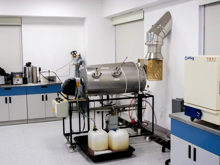
Four failure modes defeat most adhesive wastewater retrofits. Problem 1 — DAF foam carry-over: residual surfactant from the coater-cleaning cycle pushes a stable froth over the DAF weir; fix with anti-foam dosing (silicone or fatty-alcohol, 5–20 mg/L) and a 10–15 min pre-aeration cell ahead of the saturator. Problem 2 — Anaerobic reactor souring: sudden solvent spikes drive pH below 6.5 and crash methanogens; mitigation is a pH-locked equalization tank with online monitoring and a guaranteed 12 h buffer at peak flow. Problem 3 — MBR membrane fouling by emulsified polymer: residual oil and uncoagulated polymer coat the PVDF surface; specify periodic CIP every 2–4 weeks with 1,000–2,000 mg/L NaOCl plus 0.5–1% citric acid, and confirm that the upstream DAF is sized at surface loading ≤15 m/h. Problem 4 — UF flux decline from adhesive residues: emulsified polymer embeds in the UF skin layer; operate at cross-flow velocity ≥0.5 m/s with a 30-min backflush every 4 h, and install a fine screen such as the rotary mechanical bar screen ahead of the UF feed to protect against fiber carry-over.
Frequently Asked Questions
What is the typical COD range for adhesive manufacturing wastewater? Raw COD lands at 5,000–25,000 mg/L for most acrylic, PVA, and hot-melt adhesive lines, with peak spikes above 30,000 mg/L during coater-cleaning cycles (Lu et al. 2022). Design the equalization basin to dampen at least 8 h of peak flow before biological treatment.
Which treatment stages are required to reach GB 8978-1996 second-class discharge? A six-stage train — equalization, coagulation or electrocoagulation, DAF, anaerobic biofilm or UASB, MBR, and UF polish — reliably delivers COD ≤150 mg/L and SS ≤150 mg/L on a 10 m³/h PSA tape line (HydropureWater field data, 2026). RO is added only when water reuse above 70% is mandated.
Is electrocoagulation sufficient on its own for adhesive wastewater? No. Per Lu et al. 2022, electrocoagulation alone removes more than 85% of suspended solids and colloids but only 15–30% of COD; it must be paired with an anaerobic biofilm or activated-sludge stage to meet discharge limits.
What is the typical 2026 CAPEX and OPEX for a 10 m³/h adhesive wastewater plant? CAPEX for the workhorse physico-chemical + anaerobic + MBR train lands at USD 2,800–4,500 per m³/h installed; OPEX runs USD 0.6–1.8 per m³ treated (HydropureWater field data, 2026). UF-membrane concentrate trains cost 2–3× the CAPEX and suit water-reuse or ZLD projects.